
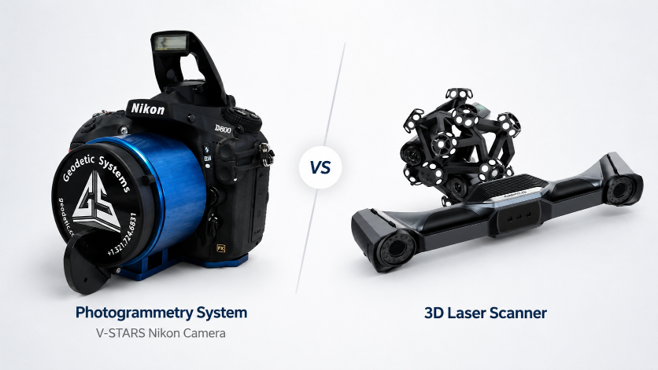
The better question is not simply, "Which technology is more accurate?"
The better question is: which measurement method is appropriate for the size, tolerance, geometry, access, environment and engineering decision involved?
Innovative Measurement Solutions uses 3D scanning, industrial photogrammetry, laser tracker measurementand controlled hybrid workflows according to the requirements of the project.
In some applications, a metrology-grade 3D scanner is the right tool. In others, photogrammetry provides a more practical way to establish or distribute dimensional references across a large structure. On complex large-volume projects, both technologies may be used together.
What Is Metrology-Grade 3D Scanning?
3D scanning captures dense surface geometry from a physical object. Depending on the system and application, the resulting measured data may be used for:
- dimensional inspection
- CAD to part comparison
- reverse engineering
- scan to CAD
- surface and profile evaluation
- tooling inspection
- as-built documentation
- fit-up analysis
- deformation analysis
- engineering visualization
One of the major strengths of 3D scanning is the amount of surface information it can capture. Instead of measuring only selected discrete points, a scanner can capture dense geometry across complex surfaces. This is especially valuable when the engineering team needs to understand shape, contour, distortion, surface variation or the complete geometry of a component.
However, scanner specification alone does not determine the quality of the final measurement. The result also depends on measurement volume, reference strategy, registration, surface condition, environment, geometry and how the data will ultimately be used.
What Is Industrial Photogrammetry?
Industrial photogrammetry uses calibrated imaging, precision targets and known scale references to determine 3D coordinates on a physical component or structure.
This is not the same thing as drone mapping or general photographic 3D reconstruction.
IMS uses industrial photogrammetry for applications including:
- large parts and structures
- dimensional control networks
- tooling
- large assemblies
- scanner referencing
- datum preservation
- deformation studies
- repeat measurement
- distributed reference networks
- large-volume metrology
Photogrammetry can be used as a standalone coordinate measurement method or as part of a larger controlled measurement strategy.
IMS has experience with GSI V STARS N and DynaMo industrial photogrammetry systems. Depending on the application, a measurement setup may include retroreflective targets, coded targets, calibrated scale bars, tooling nests and precision adapters.
The Fundamental Difference
A useful way to understand the difference is to look at the type of data each method is especially good at collecting.
3D Scanning
3D scanning is particularly valuable when the project requires dense surface geometry. Examples include:
- complex freeform surfaces
- full-surface CAD comparison
- reverse engineering
- deformation visualization
- surface inspection
- geometry reconstruction
Industrial Photogrammetry
Photogrammetry is particularly valuable when the project requires distributed coordinate references across a large or difficult measurement volume. Examples include:
- large structural measurement
- dimensional control networks
- persistent reference targets
- preserving datums during manufacturing
- working around line-of-sight limitations
- deformation or movement studies
- referencing scanner data across a large structure
Neither description means the technology is limited only to those applications. The actual measurement plan should be developed around the engineering requirement.
3D Scanning vs Photogrammetry at a Glance
| Category | 3D Scanning | Industrial Photogrammetry |
|---|
When 3D Scanning May Be the Better Fit
3D scanning becomes especially useful when the engineering question depends on detailed physical geometry. A scanner may be the better primary technology when the project requires:
- full-surface inspection
- CAD comparison
- reverse engineering
- scan to CAD
- complex surface capture
- distortion visualization
- detailed dimensional analysis
- dense geometry for engineering models
For smaller and localized applications, a metrology-grade scanner may provide the required measurement directly. As measurement volume increases, additional control strategies may become appropriate.
When Industrial Photogrammetry May Be the Better Fit
Photogrammetry becomes particularly useful when many reference points must be established across a large, complex or obstructed structure. Applications may include:
- large-volume coordinate networks
- aerospace structures
- large tooling
- datum preservation
- deformation monitoring
- repeat measurement
- scanner referencing
- long structures
- large circumferences
- areas where direct tracker line of sight is difficult
Photogrammetry can also preserve dimensional relationships through manufacturing operations when the original datum relationship was measured before a physical feature was removed and the reference target network remains stable.
Why Large Measurement Volumes Change the Answer
A small mechanical component and a structure hundreds of feet in scale are not the same measurement problem.
As measurement volume grows, dimensional control becomes increasingly important. Simply moving a scanner from one location to another does not automatically guarantee that the complete dataset maintains the required engineering relationship. Registration, environmental conditions, reference geometry and measurement strategy can all contribute to overall uncertainty.
For accuracy-sensitive large-volume scanning, IMS can establish a controlled coordinate network using laser tracker measurement. Photogrammetry can then extend distributed references across the structure while the scanner captures the detailed geometry.
When the Best Answer Is Both
Some projects benefit from combining several technologies rather than forcing the entire job through one instrument. A controlled hybrid workflow may include:
- Laser Tracker Control— a laser tracker establishes and verifies key control coordinates.
- Common Physical References— precision nests or reference locations establish relationships between measurement technologies.
- Photogrammetry Target Network— industrial photogrammetry distributes reference locations across the structure.
- Detailed 3D Scanning— the scanner captures dense surface geometry while using the distributed reference network.
- Common Coordinate Framework— measurement data can then be evaluated within the required datum or coordinate system.
Each technology performs a different job. The laser tracker supports large-volume coordinate control. Photogrammetry distributes references across the structure. The 3D scanner captures the detailed surface geometry.
The objective is not to use more equipment simply because it is available. The objective is to select a measurement strategy appropriate for the tolerance, geometry, scale, access, environment and required deliverable.
Working Around Line-of-Sight Limitations
Large structures frequently block direct visibility between an instrument and every feature that must be measured. A laser tracker requires line of sight to the target.
Photogrammetry can provide another way to carry dimensional references around a large structure. This can be useful around:
- large circumferences
- long assemblies
- obstructed structures
- aerospace hardware
- large tooling
- complex industrial components
A distributed target network can also provide independent references for scanning across these areas.
Controlling Large-Scale Scan Registration
Long, flat or repetitive structures can create registration challenges when scan alignment relies too heavily on neighboring surface geometry.
A controlled distributed reference network gives the scanner independent 3D locations throughout the measurement volume. This can help control cumulative registration error and reduce the possibility of the scan network gradually hinging, warping or drifting across a large structure.
The goal is to keep detailed scan data tied to a controlled dimensional framework rather than relying only on how neighboring scans appear to fit.
Video Photogrammetry and Industrial Photogrammetry Are Not the Same System
IMS also uses the SHINING 3D FreeScan Trak Nova, which incorporates Video Photogrammetry (VPG) within its large-object scanning workflow.
VPG should not be treated as interchangeable with GSI V STARS industrial photogrammetry. They are different systems and workflows.
Within the FreeScan Trak Nova workflow, distributed targets and a calibrated reference process can help maintain volumetric control as scanning moves across a large component. When appropriate, scanner references may also be connected to a separately established metrology control network.
What About Accuracy?
There is no responsible single accuracy number that applies to every 3D scanning project or every industrial photogrammetry project.
For 3D scanning, measurement quality may be influenced by: scanner, measurement volume, geometry, surface condition, surface reflectivity and color, distance, environment, reference network, registration strategy and intended deliverable.
For photogrammetry, measurement uncertainty may depend on: photogrammetry system, measurement volume, image geometry, target distribution, scale control, environmental conditions, network design and intended measurement.
IMS reviews these factors against the required tolerance before selecting a measurement method.
So Which One Is Better for Precision Measurement?
Neither technology is automatically better. The correct choice depends on the measurement problem. Choose the technology based on questions such as:
- Do we need dense surface geometry or primarily discrete reference coordinates?
- How large is the measurement volume?
- What tolerance must the result support?
- Is line of sight restricted?
- Does the project require reverse engineering?
- Does the structure need a distributed control network?
- Will the same references be measured again later?
- Are several measurement technologies being combined?
- What engineering deliverable is required?
A component requiring detailed CAD comparison may favor metrology-grade 3D scanning. A very large structure requiring distributed dimensional references may favor industrial photogrammetry. A large structure requiring both controlled coordinates and detailed surface geometry may benefit from a laser tracker, photogrammetry and 3D scanning working together.
The measurement strategy should follow the engineering problem.
Discuss Your Measurement Project
If you are unsure whether your project requires 3D scanning, industrial photogrammetry, laser tracker measurementor a combination of technologies, start with the engineering requirement.
Send IMS: approximate component or structure size, project location, photographs, available CAD or drawings, required tolerance, important geometry, access limitations and required deliverable. IMS can evaluate the measurement problem and recommend an appropriate approach.
Discuss Your Project Email IMS