
BIM and Digital Twins: Related Technologies, Different Purposes
Building Information Modeling and digital twins are frequently discussed together, and the overlap in terminology has created genuine confusion in the construction and engineering industries. Understanding what each term actually describes — and where the distinction matters — is useful for anyone evaluating how to apply 3D measurement data to a facility project.
BIM provides a structured digital representation of a facility. It is most commonly associated with design, construction documentation, coordination, and asset information management. A BIM model can represent what was designed, specified, or documented. What it does not automatically establish is whether installed conditions correspond to that model. The model reflects intent; the physical facility reflects what was actually built.
The term digital twin is used more broadly. In general, a digital twin describes a digital representation connected to the condition, operation, or lifecycle of a physical asset. Depending on how it is implemented, a digital twin may incorporate geometry alongside inspection records, operational data, sensor feeds, maintenance history, or other information that changes over time. Capabilities vary considerably by application — not every digital twin operates in real time or requires live sensor integration. The defining characteristic is that the digital representation maintains a meaningful relationship with the physical asset it represents, rather than serving only as a design document.
BIM and digital twins are related but not interchangeable. BIM frequently provides design and asset information that can contribute to a digital-twin environment. A digital twin can extend beyond design intent by representing and maintaining information about the physical asset throughout its operational lifecycle. The two technologies serve different purposes and are often most useful in combination.
From Design Intent to Measured Reality
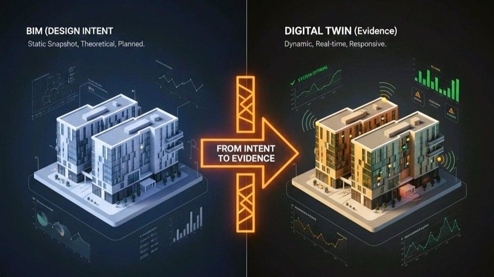
The image at the top of this article illustrates a distinction that matters practically: a BIM model represents design intent — what was planned, specified, and documented. A digital twin, at its most useful, represents evidence — what actually exists, how it performs, and how it changes over time.
The gap between those two states is where measurement becomes relevant. A facility built to a BIM model may correspond closely to the design, or it may not. Dimensional variation, field modifications, as-built deviations, and the accumulated changes of renovation and maintenance all mean that the physical facility and the design model can diverge. Accurate spatial data is what bridges that gap — it provides the measured evidence needed to determine how closely actual installed conditions correspond to the design or BIM model.
This is not a criticism of BIM. Design models serve their intended purpose well. The point is that a model representing design intent and a model representing measured physical conditions are different things, and treating them as equivalent can lead to problems downstream — particularly when decisions about renovation, equipment installation, or facility modification depend on accurate as-built geometry.
In practice, many facilities have BIM models that were accurate at the time of construction but have not been updated to reflect subsequent modifications, repairs, or equipment changes. When a project team needs to plan new work within that facility, the question is not whether a BIM model exists — it is whether the model reflects current conditions. That question can only be answered by measurement.
Where 3D Laser Scanning Fits
Terrestrial 3D laser scanning captures existing physical conditions by collecting dense spatial measurement data across a facility or structure. The resulting point cloud represents the geometry of the space as it actually exists at the time of measurement. That data can then be compared with drawings or models, processed into existing-condition documentation, or used as the geometric foundation for a scan-to-BIM workflow.
Practical applications include:
- Existing-condition documentation — capturing accurate as-built geometry of facilities where original drawings are incomplete, outdated, or unavailable
- Scan to BIM — converting measured point cloud data into a structured BIM model that reflects actual installed conditions rather than design intent
- Construction verification — comparing installed work against design models to identify deviations before they create downstream problems
- Dimensional comparison — quantifying how closely physical conditions match drawings, specifications, or reference geometry
- Renovation and retrofit planning — providing accurate spatial context for work that must fit within or connect to existing structure
- Installation and interference analysis — verifying that new equipment or assemblies will fit within the actual space before fabrication or delivery
- Facility documentation — creating a measured record of a facility's geometry for asset management, maintenance planning, or future project use
- Complex geometry capture — documenting curved surfaces, irregular structures, or congested mechanical spaces where traditional manual measurement is impractical
Laser scanning provides the measured physical evidence needed to determine how closely the actual facility corresponds to the design or BIM model. It does not by itself create a complete digital twin — scanning supplies geometric and spatial information that may become one component of a broader digital-twin system, alongside operational data, inspection records, and other information sources.
Scan to BIM in Practice
A scan-to-BIM workflow begins with field scanning and ends with a model that reflects measured conditions. The point cloud captured during scanning is registered, cleaned, and used as the reference geometry from which the BIM model is built or updated. The resulting model carries the accuracy of the measurement rather than the assumptions of the original design.
This matters most when the gap between design and reality is unknown or suspected to be significant. Renovation projects, equipment replacement, systems coordination in existing facilities, and any work that requires precise spatial clearances all benefit from a model grounded in measured data. Working from an unverified design model in those situations introduces risk that field measurement can eliminate.
Construction Verification and Deviation Analysis
Scanning during or after construction allows installed conditions to be compared directly against the design model. Deviations can be identified, quantified, and documented before they affect downstream work. In complex projects — particularly those involving prefabricated components, modular assemblies, or tight spatial tolerances — catching dimensional issues early is substantially less costly than discovering them during installation or commissioning.
3D laser scanning captures the full geometry of the installed work in a single field operation, producing a record that can be analyzed against the model and archived for future reference. That record also has value beyond the immediate project — it becomes part of the facility's documented history.
Accuracy and What the Application Actually Requires
Required measurement accuracy depends on the application, and it is worth being specific about this. A general facility model intended for visualization, space planning, or renovation coordination does not necessarily require the same measurement uncertainty as dimensional inspection, equipment alignment, fabrication verification, or precision installation work.
Terrestrial laser scanning is well suited to existing-condition documentation, scan-to-BIM, construction verification, and facility documentation where the required accuracy is consistent with what scanning can reliably deliver. For applications requiring tighter tolerances — precision alignment, dimensional inspection to engineering specifications, fabrication verification, or work where measurement uncertainty must be formally characterized — higher-precision metrology methods are more appropriate.
Laser tracker measurement and dimensional inspection address those higher-precision requirements. IMS provides both scanning and precision metrology services, which means the measurement approach can be matched to what the project actually requires rather than applying a single method to every situation.
Understanding this distinction matters when evaluating measurement data for use in a digital-twin environment. Geometry captured for general facility documentation and geometry captured for precision alignment or fabrication verification represent different levels of measurement rigor, and a digital-twin system that depends on accurate physical data should reflect that difference. The value of the digital representation is only as good as the quality of the measurement data it is built from.
IMS and 3D Measurement for Construction and Engineering
Innovative Measurement Solutions provides professional 3D measurement and metrology services supporting construction, engineering, manufacturing, and industrial applications. IMS is based in Florida and provides services throughout Florida, nationally, and internationally where project requirements call for it.
For construction and facility projects, IMS's scanning services can support existing-condition documentation, scan-to-BIM workflows, construction verification, and the spatial measurement work that connects design models to physical reality. Where projects require precision metrology beyond what scanning provides, IMS's laser tracker and dimensional inspection capabilities address those requirements.
If you are working on a project that involves existing-condition documentation, BIM coordination, facility renovation, or any application where accurate spatial data matters, contact IMS to discuss your measurement requirements.