
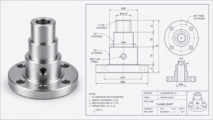
CAD defines what engineering intends. Manufacturing produces what physically exists. Between those two things — the nominal model and the finished hardware — there is always some difference. The question is whether that difference is understood, evaluated against the applicable requirement, and acted on appropriately.
Metrology is the discipline that connects the physical result back to the engineering definition. The loop it closes looks like this:
Design → Manufacture → Measure → Compare → Understand → Adjust or Verify
Not every deviation requires adjustment. Not every difference from nominal CAD is a nonconformance. What matters is whether the measured condition meets the applicable drawing, tolerance, GD&T requirement, or customer specification — and whether that determination is based on defensible measurement data.
What Is CAD-to-Part Inspection?
CAD-to-part inspection is the process of comparing measured physical geometry with nominal engineering geometry to evaluate dimensional deviation. The measured data — collected by laser tracker, 3D scanner, photogrammetry, or other appropriate instrument — is aligned to the engineering coordinate system and evaluated against the CAD model, drawing, or specification.
Depending on the engineering requirement, the evaluation may involve:
- Discrete features: holes, bores, planes, surfaces, edges, and defined points
- XYZ coordinates and distances
- Dimensions and tolerances from engineering drawings
- GD&T callouts: flatness, perpendicularity, true position, profile, and others
- Full-surface comparison against CAD, producing deviation color maps
- Profile evaluation across complex geometry
Full-surface scanning is not required for every inspection. Many applications are well served by discrete feature measurement. The appropriate approach depends on what the engineering requirement actually asks for.
CAD Represents Intent — Measurement Represents Condition
Nominal CAD is the intended engineering geometry. It represents what the designer specified. The as-built or measured condition is the geometry that physically exists after manufacturing, assembly, or installation.
These are not the same thing, and the distinction matters. A measured component should not automatically be assumed defective simply because some surface differs from nominal CAD. Manufacturing variation is normal. The relevant question is whether the measured condition conforms to the applicable acceptance criteria — the drawing, the tolerance, the GD&T callout, the customer requirement.
Acceptance decisions must be based on the applicable engineering definition, not on visual similarity to the CAD model or on the magnitude of deviation alone.
The Closed Manufacturing Loop
The value of dimensional measurement in manufacturing comes from its role in a feedback loop:
- Engineering definition establishes what is required.
- Manufacturing produces the hardware.
- Dimensional measurement characterizes the physical condition.
- CAD or drawing comparison evaluates the measured condition against the requirement.
- Engineering interpretation determines what the result means for the project.
- Corrective action, acceptance, or further verification follows as appropriate.
- Re-measurement confirms the result where required.
Measurement provides objective information for decisions. It does not automatically determine root cause. A deviation map shows where a surface is high or low relative to nominal. It does not, by itself, explain why — that requires engineering analysis of the manufacturing process, tooling condition, material behavior, and other factors.
Measurement Strategy Before Equipment
IMS approaches CAD-to-part inspection with a strategy-first philosophy. The engineering requirement determines the measurement method — not the other way around.
Factors that inform method selection include:
- The tolerance and how it compares to achievable measurement uncertainty
- Component size and measurement volume
- Feature geometry and surface condition
- Accessibility and line-of-sight constraints
- Environmental conditions
- Required point density or surface coverage
- The engineering coordinate system and datum strategy
- Required deliverables — report format, color map, GD&T results, alignment record
No single instrument is universally best. The right choice depends on what the project actually requires.
Discrete Inspection vs. Full-Surface CAD Comparison
These are two distinct approaches, and understanding the difference helps in selecting the right one.
Discrete measurement evaluates specific holes, planes, bores, points, distances, positions, alignments, and defined features. It is appropriate when the engineering requirement specifies particular dimensions, GD&T callouts, or feature relationships. It is efficient and directly tied to the drawing.
Full-surface comparison captures dense measured geometry and evaluates it against CAD across the entire surface or a defined region. The result is typically a color deviation map showing where the measured surface is above or below nominal. This approach is useful for visualizing:
- Bowing, twisting, or warping across a panel or structure
- Localized high or low areas
- Surface deformation from welding, forming, or assembly
- Interface mismatch between mating components
- Feature displacement across a large assembly
- Assembly distortion relative to nominal geometry
Deviation patterns can help engineers investigate a condition, but the measurement data alone does not establish root cause. The color map shows what — engineering analysis determines why.
Coordinate Systems and Datum Strategy
CAD comparison is only meaningful when the measured data and the engineering definition are aligned in an appropriate coordinate framework. Evaluating a component in the wrong coordinate system can produce results that appear to show a problem where none exists — or miss a real one.
Engineering drawings and CAD models define dimensions and tolerances relative to specific datums. The measurement coordinate system must correspond to the engineering datum reference frame. This means identifying the correct datum features, measuring them with appropriate care, and establishing the coordinate system in a way that matches the drawing intent.
Best-fit alignment — where the measured data is mathematically aligned to minimize overall deviation — is a useful tool in some applications, but it is not automatically the correct engineering alignment. A best-fit result may distribute deviation across the part in a way that does not reflect how the part is actually constrained in use. The alignment strategy should match the engineering requirement.
For a detailed treatment of coordinate systems in dimensional measurement, see the IMS article on why coordinate systems matter in laser tracker measurement.
In-Process Inspection
Measurement during manufacturing can provide information while corrective options may still be available. Waiting until a component is complete before measuring means that any dimensional condition found at that point must be addressed after the fact — through rework, engineering disposition, or rejection.
In-process inspection can be applied at various stages:
- Fabrication verification during forming, welding, or machining
- Machining setup confirmation before a critical operation
- Tooling adjustment based on measured component geometry
- Component alignment verification before assembly proceeds
- Interface verification between mating structures
- Assembly positioning and integration checks
- Weldment inspection before post-weld operations
- Large assembly integration verification at defined milestones
In-process inspection does not guarantee that no rework will be required. It provides dimensional information at a point in the process where the team still has options. What happens with that information is an engineering and production decision.
Final Dimensional Verification
Final inspection after manufacturing, assembly, installation, or adjustment establishes the dimensional condition of the finished work. It provides the basis for acceptance, delivery, or further action.
Final verification evaluates the measured condition against:
- CAD model and nominal geometry
- Engineering drawings and tolerances
- GD&T callouts and datum reference frames
- Customer requirements and acceptance criteria
- Applicable standards or specifications
Acceptance requirements should be established before inspection where practical. Defining what constitutes acceptance after a result is already known introduces ambiguity and can create disputes. Agreeing on the acceptance criteria in advance — what will be measured, how it will be evaluated, and what constitutes a conforming result — supports a cleaner inspection process and clearer engineering decisions.
When the Original CAD Does Not Exist
Legacy, obsolete, or modified components may not have usable CAD. The original design documentation may be incomplete, unavailable, or may not reflect the current physical condition of the part. In these cases, the measurement-to-CAD workflow runs in reverse: the physical component is measured first, and the CAD is derived from that measurement.
The IMS reverse engineering workflow can include:
- Physical component measurement
- Reconstructed CAD model development
- Verification of the reconstructed model against the original measurement data
- Drawing or manufacturing data production
- Replacement component manufacturing
- Final inspection of the replacement against the engineering definition
Two distinct model types are relevant here. An as-built model represents the measured physical condition — it captures what the part actually is, including any wear, deformation, or manufacturing variation. A design-intent model reconstructs the intended engineering geometry based on the project requirement — it represents what the part was meant to be, with nominal features, clean geometry, and appropriate tolerances. These are not interchangeable. Which type is needed depends on the engineering purpose of the model.
Verifying Reconstructed CAD
Reverse engineering should not stop simply because a CAD model visually resembles the scan data. Visual similarity is not dimensional verification.
The reconstructed model can be compared back against the original measurement data using the same deviation analysis used in forward inspection. This comparison evaluates how well the reconstructed geometry represents the measured component — where the model matches the scan closely, and where it diverges.
The acceptable level of deviation between the reconstructed model and the original measurement depends on the intended engineering use. A model being used to manufacture a replacement part has different verification requirements than one being used for documentation or reference. Establishing those requirements before reconstruction begins — rather than after — supports a more useful verification process.
Tooling as Part of the Loop
Manufacturing variation may involve not only the part but also the tooling or fixture that controls it. A tool that has worn, shifted, or been incorrectly set can produce dimensional conditions in the part that reflect the tool's condition rather than a process error.
IMS tooling and fixture certification supports evaluation of tooling geometry against:
- CAD and nominal geometry
- Engineering drawings and datums
- Master references
- Accepted production geometry where appropriate
Measurement can help determine whether tooling geometry may be contributing to a dimensional condition observed in production. It does not automatically prove causation — that requires engineering analysis of the full process. But it provides objective data that supports the investigation.
Choosing the Right Metrology Technology
Different measurement technologies serve different roles in CAD-to-part inspection:
- Laser tracker measurement — large-volume coordinate measurement, tooling evaluation, alignment, and discrete feature inspection. Well suited to aerospace structures, large assemblies, and precision alignment applications where defined features and coordinate accuracy are the primary requirement.
- 3D laser scanning — dense surface geometry capture for full-surface CAD comparison, reverse engineering, and complex shape evaluation. Useful when surface coverage and deviation mapping are required.
- Industrial photogrammetry — distributed measurement and reference network applications for large or geometrically complex structures where line of sight from a single position is limited.
- Dimensional inspection — the engineering evaluation workflow that applies one or more measurement technologies to evaluate a component against its engineering definition. The technology serves the inspection; the inspection serves the engineering requirement.
These are not competing options — they are complementary tools. Many projects use more than one. The selection depends on what the engineering requirement asks for.
From Measurement Data to Engineering Information
Raw point clouds and coordinate data are not always the final useful deliverable. The engineering team typically needs information — results that can be evaluated against a requirement and used to support a decision.
Depending on the project requirement, IMS deliverables can include:
- Dimensional inspection reports with feature measurements and tolerances
- GD&T results evaluated against drawing callouts
- Ballooned drawing results
- CAD-to-part comparison with full-surface color deviation maps
- Deviation callouts at specific features or regions
- XYZ coordinate data and feature measurements
- Alignment results and coordinate system documentation
- Graphical reporting for engineering review
- Customer-specific formats where required
Reporting should match the engineering decision being made. A report that answers the question the project is actually asking is more useful than one that simply documents that measurement occurred.
Why Closing the Loop Matters
A closed measurement loop — where dimensional data flows from manufacturing back to the engineering definition and informs decisions — can help teams:
- Verify that manufactured geometry meets the engineering requirement
- Identify dimensional conditions at a point in the process where options still exist
- Evaluate tooling relationships and their potential contribution to observed conditions
- Provide objective data for engineering investigation and disposition
- Verify corrective work after adjustment or rework
- Maintain traceable dimensional records across the project
- Compare replacement components against the engineering definition
None of these outcomes are guaranteed by measurement alone. They depend on measurement that is planned appropriately, executed with the right method, evaluated in the correct coordinate framework, and reported in a way that supports the engineering decision.
Engineering Takeaway
CAD describes what engineering intends. Metrology establishes what physically exists. Comparison connects the two.
The value of closed-loop dimensional verification comes from turning defensible measurement data into engineering information that supports manufacturing decisions — not from measurement as an end in itself.
IMS develops measurement strategies around the engineering requirement. The approach is: understand the question, measure appropriately, analyze against the applicable definition, and deliver results that support the decision. If you have a CAD-to-part inspection, dimensional verification, or reverse engineering application, contact IMS to discuss the project.