
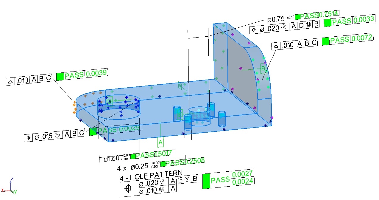
A measurement result is not simply a number. It is information that drives a decision — whether to accept or reject a part, whether to adjust a machine, whether to proceed with assembly, whether to release a component to the next stage of production. When that information is unreliable, the decisions it supports may be unreliable too. The consequences can appear anywhere downstream: unnecessary rework, incorrect adjustments, assembly problems, repeated inspection, or engineering investigation that traces back to a measurement that was not as trustworthy as it appeared.
The real cost of poor measurement is not the numerical error itself. It is the manufacturing decision that was made on the basis of that error.
Measurement Error vs. Measurement Uncertainty
These two terms are related but distinct, and the distinction matters in practice.
Measurement error is the difference between a measured result and the reference or true value of the quantity being measured — where that reference value can be meaningfully established. In calibration, for example, a known reference artifact allows the error of an instrument to be characterized.
Measurement uncertainty is something different: it is a quantified expression of the doubt associated with a measurement result. It does not describe a single known error. It characterizes the range within which the true value is reasonably expected to lie, given everything that is known about the measurement process.
In normal manufacturing inspection, the exact measurement error is generally not known. The reference value is not sitting next to the part for comparison. This is precisely why uncertainty matters — it provides a framework for understanding how much confidence can be placed in the result, even when the true value cannot be independently verified.
Describing uncertainty simply as "measurement error" understates what it represents and can lead to underestimating its significance in conformance decisions.
Why Instrument Accuracy Is Not the Whole Measurement
A manufacturer's instrument specification — the accuracy or volumetric performance figure published in a datasheet — describes the instrument under defined conditions. It is one input to the total measurement uncertainty. It is not the total measurement uncertainty.
In a real field measurement, additional contributors can include:
- Measurement distance and working volume
- The geometry of the features being measured and the instrument positions used
- Environmental conditions — temperature, vibration, air turbulence
- Component temperature and the thermal state of the part at the time of measurement
- Material behavior and coefficient of thermal expansion
- Line of sight and access constraints
- Setup and fixturing
- Reference network design and quality
- Registration strategy for multi-position measurements
- Coordinate system and datum establishment
- Target or probe configuration
- Component stability during measurement
- Measurement procedure and, where applicable, operator factors
Each of these can contribute to the uncertainty of the final result. Some are small and well-controlled. Others can be significant, particularly in large-volume or field measurement environments. The instrument specification alone does not tell you which contributors are dominant in your specific application.
This is why the measurement strategy — how the measurement is planned, set up, and executed — matters as much as the instrument selected.
How Measurement Problems Affect Manufacturing Decisions
Consider a few realistic scenarios, not invented case studies, but the kinds of situations that arise in dimensional inspection and manufacturing metrology:
A feature measured near a tolerance boundary. A dimension is reported as 0.003 mm inside the upper tolerance limit. The part is accepted. But if the measurement uncertainty is comparable to that margin, the result does not clearly distinguish a conforming part from a nonconforming one. The acceptance decision rests on a result that may not have the resolution to support it.
A tooling adjustment based on incorrect dimensional information. A machine is adjusted based on a measured offset. If the measurement that drove the adjustment was affected by a setup error, a temperature effect, or a coordinate system problem, the adjustment may move the process in the wrong direction — or introduce a new error while correcting a phantom one.
Alignment performed in the wrong coordinate system. A component is aligned to a high degree of repeatability — but to the wrong reference. The measurement is precise. The engineering conclusion is wrong. Repeatability and accuracy are not the same thing, and a measurement can be highly repeatable while still being systematically offset from the intended reference.
A component changing dimension with temperature. A large steel structure is measured in the morning when the facility is cool. By afternoon, the temperature has risen and the structure has expanded. If the measurement is used to make a fit-up or alignment decision without accounting for the thermal state of the part, the result may not represent the condition at the intended reference temperature.
A registration or network problem in large-volume measurement. Multiple instrument positions are combined to cover a large structure. If the reference network that ties those positions together has errors — from insufficient target coverage, poor geometry, or unstable reference points — those errors propagate into every measurement made from that network.
In each case, the consequence is not just a number that is slightly wrong. It is a decision — about acceptance, adjustment, alignment, or assembly — that may be wrong in a way that is not immediately visible.
False Acceptance and False Rejection
When measurement uncertainty is not considered in conformance decisions, two types of errors can occur.
False acceptance occurs when a part or condition is judged conforming when it should not be. The measured result falls inside the tolerance, but the true value — accounting for measurement uncertainty — may lie outside it. The part proceeds to the next stage of production or is shipped to the customer.
False rejection occurs when a conforming part is judged nonconforming. The measured result falls outside the tolerance, but the true value may actually be within it. The part is scrapped, reworked, or subjected to engineering disposition — unnecessarily.
Both outcomes have consequences. False acceptance can result in nonconforming product reaching assembly or the customer. False rejection wastes conforming parts and production time.
When a measurement result lies comfortably inside or outside a tolerance — well away from the specification limit — the uncertainty may not materially affect the decision. When a result lies near the boundary, uncertainty becomes directly relevant to whether the decision is reliable.
Conformance decision rules — how uncertainty is handled at the tolerance boundary — should be established according to the applicable engineering or quality requirement. Standards such as ASME B89.7.3.1 address the relationship between measurement uncertainty and conformance decisions. The appropriate approach depends on the specific application and the agreement between the parties involved. IMS does not apply a universal guard-band rule across all projects; the right approach is determined by the engineering requirement.
Temperature and Material Behavior
Dimensional measurements are sensitive to temperature because materials expand and contract with temperature change. The coefficient of thermal expansion (CTE) describes how much a material's dimensions change per unit of temperature change per unit of length. Steel, aluminum, titanium, and composite materials all have different CTE values, and the same temperature change will produce different dimensional effects in different materials.
For large components or structures, even a modest temperature difference between the part and the nominal reference temperature (typically 20°C / 68°F in dimensional metrology) can produce dimensional changes that are significant relative to the tolerance being evaluated. The larger the part and the tighter the tolerance, the more important temperature becomes.
Temperature compensation — adjusting measured values to account for thermal expansion — requires appropriate temperature information and accurate material property data. It reduces the thermal contribution to uncertainty, but it does not eliminate it. Uncertainty in the temperature measurement itself, variation across a large structure, and uncertainty in the material's actual CTE all remain as contributors. Temperature compensation is a tool, not a guarantee.
For more on how thermal effects interact with large-volume measurement, see the IMS article on thermal effects and measurement uncertainty in large-scale metrology.
Coordinate Systems and Datums
A measurement can be highly repeatable and still support a wrong engineering conclusion if it is evaluated in an inappropriate coordinate framework.
Engineering drawings and CAD models define dimensions and tolerances relative to specific datums — reference features that establish the coordinate system for the part or assembly. When a measurement is performed, the coordinate system used to evaluate the results must correspond to the engineering intent. If the wrong features are used to establish the coordinate system, or if the datum strategy does not match the drawing, the measured values may not represent what the drawing requires — even if the instrument performed correctly.
This matters particularly in large-volume measurement, where establishing and maintaining a consistent coordinate framework across multiple instrument positions and large working volumes requires deliberate planning. Tooling points, datum surfaces, bore centerlines, and other reference features must be measured with appropriate care, because errors in the datum establishment propagate through the entire analysis.
For a detailed treatment of coordinate systems in laser tracker measurement, see the IMS article on why coordinate systems matter in laser tracker measurement.
Large-Volume Measurement
Measurement uncertainty becomes especially important — and more complex to manage — when measuring large tooling, aircraft and aerospace structures, large machinery, industrial assemblies, and facility structures.
Several factors contribute to this:
- Distance: Most measurement instruments have uncertainty that increases with working distance. A specification that applies at close range may not apply at the working distances required for a large structure.
- Multiple instrument positions: Large structures often cannot be measured from a single instrument position. Each additional setup introduces registration uncertainty — the error in how the positions are tied together.
- Reference and control networks: A well-designed reference network — stable, well-distributed reference points that tie multiple measurement positions into a common coordinate framework — is essential for large-volume work. Network geometry, target coverage, and stability all affect the quality of the result.
- Environmental effects: Temperature gradients, air turbulence, vibration, and facility conditions can all affect measurement results over large volumes and extended measurement sessions.
- Geometry: The angular geometry of measurements — the angles at which targets are observed from instrument positions — affects the uncertainty of the derived coordinates. Poor geometry amplifies uncertainty; good geometry constrains it.
For large-volume applications, the measurement strategy — instrument selection, network design, setup geometry, environmental management — has a larger effect on the achievable uncertainty than the instrument specification alone. IMS does not publish a universal accuracy figure for large-volume work because the achievable uncertainty depends on the specific application. For more on this topic, see the IMS article on how accurate is a laser tracker.
Calibration Is Necessary — But Not Sufficient
Instrument calibration and metrological traceability are important. A calibrated instrument with a documented calibration chain to national or international measurement standards provides confidence that the instrument's performance is characterized and that its results are traceable. This is a baseline requirement for credible measurement.
But calibration characterizes the instrument under defined conditions. It does not automatically account for every uncertainty contributor in the actual field measurement. The environmental conditions, the setup, the reference network, the coordinate system, the measurement procedure — none of these are addressed by the instrument calibration alone.
A calibrated instrument used with a poor measurement strategy can still produce results with significant uncertainty. Calibration is a necessary condition for reliable measurement. It is not a sufficient one.
Selecting the Measurement Method Around the Engineering Requirement
IMS approaches measurement projects with a strategy-first philosophy: define the engineering question before selecting the equipment. The measurement method should be chosen based on what the project actually requires, not on what instrument is most familiar or most available.
Factors that should inform method selection include:
- The tolerance and how it compares to the achievable measurement uncertainty
- Component size and measurement volume
- Feature geometry and surface condition
- Accessibility and line-of-sight constraints
- Environmental conditions
- Required point density or coverage
- The engineering coordinate system and datum strategy
- Required deliverables — report format, CAD comparison, deviation map, alignment record
IMS uses several measurement technologies, selected based on the application:
- Laser tracker measurement — large-volume coordinate measurement, alignment, and dimensional control. Well suited to aerospace structures, large assemblies, tooling, and precision alignment applications.
- 3D laser scanning — dense surface geometry capture. Useful for CAD-to-part comparison, as-built documentation, and applications requiring full surface coverage.
- Industrial photogrammetry — distributed measurement and control for large or geometrically complex structures. Particularly useful for establishing reference networks and capturing geometry where line of sight from a single position is limited.
- Dimensional inspection — engineering evaluation against CAD, drawings, GD&T, or applicable requirements. The evaluation framework that ties measurement results to the engineering requirement.
No single technology is universally superior. The right choice depends on the application.
Measurement Uncertainty and Conformance Decisions
When a measurement result lies comfortably inside a tolerance — well away from the specification limit — the uncertainty may not materially affect the conformance decision. The result clearly indicates conformance regardless of the uncertainty range.
When a result lies near the specification boundary, the situation is different. The uncertainty range may overlap the tolerance limit. The measurement result alone may not be sufficient to determine whether the true value is inside or outside the tolerance. In this situation, the decision rule — how the organization handles results near the boundary — becomes important.
Customer and supplier agreement on acceptance criteria and decision rules matters precisely because of this. If one party assumes that a result at the tolerance limit is acceptable and the other assumes it is not, the measurement result does not resolve the disagreement — the decision rule does. Establishing that agreement before inspection, rather than after a borderline result is reported, avoids disputes and supports consistent quality decisions.
IMS does not apply a universal uncertainty ratio requirement across all projects. The appropriate approach is determined by the engineering requirement and the applicable standard or agreement for the specific application.
What Good Measurement Planning Looks Like
A practical measurement planning checklist for manufacturing and inspection applications:
- Define the engineering question — what decision will this measurement support?
- Identify the applicable drawing, CAD model, or specification.
- Establish the tolerance and acceptance requirements.
- Define the coordinate system and datums.
- Select appropriate measurement technology for the application.
- Evaluate geometry and access constraints.
- Consider environmental conditions and temperature management.
- Establish a reference or control strategy where required.
- Determine required reporting format and deliverables.
- Consider measurement uncertainty relative to the tolerance and the decision being made.
This sequence is not bureaucratic overhead. It is the difference between a measurement that supports a reliable engineering decision and one that produces a number without adequate context.
The Real Cost of Inaccurate Measurement
The legacy framing of this topic — that measurement errors "multiply into millions" — overstates what can be claimed without documented evidence. But the underlying concern is real.
Measurement information drives manufacturing decisions. When that information is unreliable — because of poor measurement strategy, uncontrolled uncertainty contributors, inappropriate coordinate systems, or inadequate planning — the decisions it supports may be unreliable too. The consequences can appear as:
- Unnecessary rework on conforming parts
- Unnecessary scrap
- Incorrect machine or tooling adjustments
- Assembly problems traced back to a measurement decision
- Repeated inspection to resolve a result that was not trustworthy the first time
- Engineering investigation and disposition
- Production delays
- Supplier and customer disagreement over borderline results
- Unreliable quality records
None of these consequences require a dramatic dollar figure to be significant. They are the ordinary downstream effects of measurement information that was not adequate for the decision it was asked to support.
Engineering Takeaway
Good metrology is not about producing the smallest possible number. It is about producing measurement information with enough confidence, traceability, and engineering context to support the decision being made.
That means understanding what the measurement is for before selecting how to perform it. It means designing the measurement strategy around the engineering requirement — the tolerance, the coordinate system, the environment, the scale — rather than defaulting to the most familiar instrument. It means recognizing that calibration is a starting point, not a complete answer.
IMS develops measurement strategies around the engineering requirement. If you have a dimensional inspection, alignment, or large-volume measurement application where measurement uncertainty is a factor in the decision, contact IMS to discuss the project.