
In precision manufacturing, a tolerance and a measurement result are not the same thing — and treating them as interchangeable is one of the most common sources of inspection problems. A tolerance defines the allowable variation in a manufactured feature or relationship. A measurement result is the value or geometry obtained through inspection. Whether that result demonstrates conformance depends on a third factor: the measurement strategy used to obtain it.
This distinction matters because the measurement method must be selected around the engineering requirement, not simply around whatever equipment is available. The sections below explain why, and what that means in practice for dimensional inspection, technology selection, and metrology planning.
What Is an Engineering Tolerance?
Every manufactured feature has a nominal geometry — the intended size, shape, position, or relationship defined by the engineering design. A tolerance defines how much the actual feature is permitted to deviate from that nominal condition and still satisfy the engineering requirement.
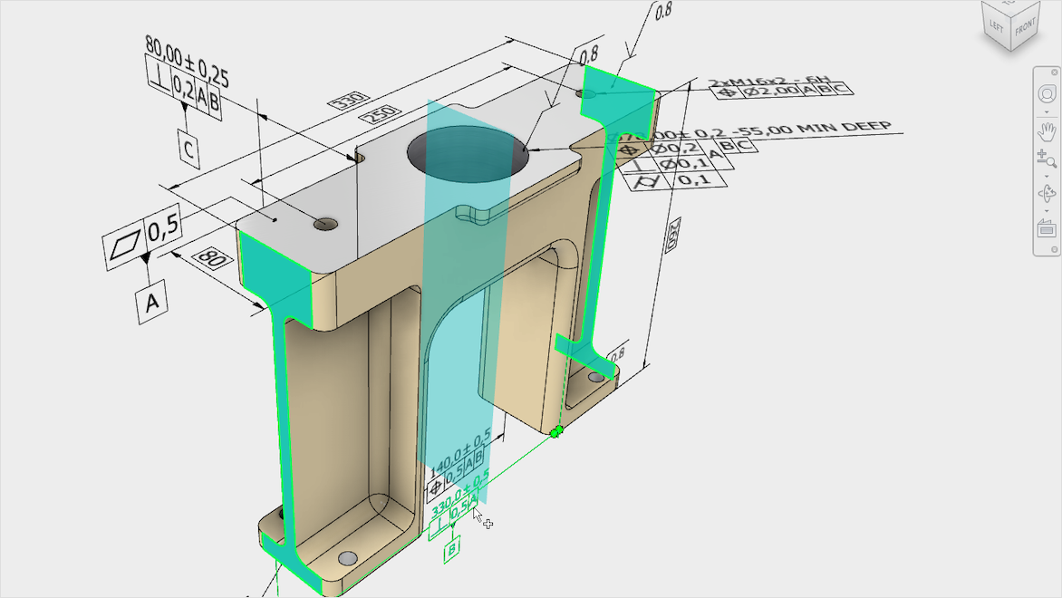
A shaft diameter might be specified as 50.000 mm with a bilateral tolerance of ±0.025 mm. A bolt hole pattern might carry a positional tolerance controlling where each hole center may fall relative to defined datums. A mating surface might be controlled for flatness within a specified zone. In each case, the tolerance communicates the boundary of acceptable variation — not a target to hit exactly, and not a number that describes how the part will be measured.
Understanding what the tolerance is actually controlling — size, position, orientation, form, profile, runout, or a relationship between features — is the starting point for any measurement plan.
Why Tolerance Drives Inspection Strategy
The engineering requirement should drive the measurement plan. This means that before selecting an instrument or defining a sampling strategy, the measurement team needs to understand what is being controlled, how tight the tolerance is, what the component looks like, where it will be measured, and what the deliverable needs to be.
Tighter tolerances generally place greater demands on the measurement process across multiple dimensions: measurement capability, measurement uncertainty, environmental control, fixturing and component stability, coordinate system and datum establishment, measurement geometry, sampling strategy, inspection planning, reporting, and conformance decisions. None of these factors operates independently. A measurement process that performs well under controlled laboratory conditions may behave differently in a production environment or in the field.
Feature type also matters. Measuring a simple linear dimension is a different problem from evaluating the position of a hole pattern relative to a datum reference frame, or assessing the profile of a complex surface against a CAD nominal. The inspection plan needs to reflect what the engineering drawing or model-based definition is actually asking.
GD&T Changes What Must Be Measured
Geometric Dimensioning and Tolerancing (GD&T), as defined in ASME Y14.5, provides a standardized language for communicating allowable geometric variation on engineering drawings and model-based definitions. GD&T controls characteristics such as size, position, orientation, form, profile, and runout — each relative to defined features and datums.
Where GD&T is used, size alone is not sufficient to evaluate conformance. A hole that is the correct diameter may still fail a positional tolerance if its center is not within the specified tolerance zone relative to the datum reference frame. A surface that appears visually flat may not satisfy a flatness or profile tolerance when measured against the engineering requirement.
This is why inspection must interpret the actual engineering requirement rather than simply comparing arbitrary points to CAD. The measurement must be set up to evaluate what the tolerance is controlling — which requires understanding the datum structure, the applicable tolerance type, and the geometry of the feature being inspected. Dimensional inspection at IMS is planned around the engineering requirement, not around a generic measurement routine.
Tolerance and Measurement Uncertainty Are Not the Same Thing
This is one of the most important distinctions in applied metrology, and one of the most frequently overlooked.
A tolerance is an engineering specification. It defines the permitted variation in the manufactured feature. Measurement uncertainty is a property of the measurement process — it quantifies the doubt associated with the measurement result. These are separate quantities, and confusing them leads to poor inspection planning and unreliable conformance decisions.
Measurement uncertainty can be influenced by many contributors, including instrument performance, measurement geometry, distance from the instrument to the target, environmental conditions, temperature and thermal gradients, material behavior, reference network quality, target or probe configuration, component stability during measurement, operator technique and method, coordinate system establishment, and the overall measurement strategy. No single contributor dominates in every application. The relative importance of each depends on the specific measurement task.
General guidance on evaluating and expressing measurement uncertainty is provided in NIST Technical Note 1297, Guidelines for Evaluating and Expressing the Uncertainty of NIST Measurement Results. This document does not prescribe a universal uncertainty value for any instrument or application — it provides a framework for understanding and quantifying uncertainty contributors in a given measurement process.
Why Instrument Accuracy Is Only Part of the Measurement
An instrument specification sheet describes the performance of the instrument under defined conditions. It does not describe the uncertainty of every completed field measurement using that instrument.
A laser tracker, for example, has published volumetric accuracy specifications. Those specifications apply under specific conditions — typically including a defined measurement volume, a stable thermal environment, a well-established reference network, and appropriate measurement geometry. In a production environment or field application, conditions may differ. Thermal gradients, component movement, line-of-sight constraints, reference network geometry, and measurement distance all influence the actual uncertainty of the result.
The same applies to 3D laser scanning, industrial photogrammetry, and any other measurement technology. Calibration is necessary — it establishes that the instrument is performing within its specified parameters — but calibration alone does not establish that a measurement process is suitable for every tolerance or every application. Suitability depends on the full measurement process, not the instrument in isolation.
What Happens Near a Tolerance Limit?
A measurement result that falls well inside a tolerance zone presents a straightforward conformance decision. A result near the tolerance boundary requires more consideration.
When a measured value is close to the specification limit, measurement uncertainty becomes directly relevant to the conformance decision. A result that appears to be just inside the tolerance may, when uncertainty is considered, be consistent with a true value that falls outside. A result just outside the tolerance may similarly be consistent with a conforming true value. This is the practical problem of false acceptance and false rejection.
ASME B89.7.3.1, Guidelines for Decision Rules: Considering Measurement Uncertainty in Determining Conformance to Specifications, addresses this issue by providing guidance on decision rules that account for measurement uncertainty when determining conformance. The appropriate decision rule for a given application depends on the quality requirements, the applicable standard or contract, and the risk tolerance of the parties involved. IMS does not prescribe a universal decision rule — the applicable rule is determined by the engineering and quality requirements of the specific project.
Choosing the Right Measurement Technology
No single measurement technology is universally more accurate or more appropriate than another. Technology selection depends on the application — the tolerance, the component geometry, the measurement volume, the environment, the required data type, and the deliverable.
Laser tracker measurement is well suited to large-volume coordinate measurement, precision alignment, tooling and fixture certification, assembly verification, and applications requiring discrete point or feature measurement across large structures. IMS provides laser tracker measurement services for aerospace, defense, industrial, and other precision applications.
3D laser scanning provides high-density surface capture, as-built geometry, deviation analysis against CAD, and broad geometric coverage of complex surfaces. It is appropriate where the engineering requirement involves surface form, profile, or geometry that cannot be adequately characterized by discrete point measurement. IMS provides 3D laser scanning services across a range of industries and component types.
Industrial photogrammetry can be effective for large structures and distributed coordinate networks where the application supports it. IMS provides industrial photogrammetry services where this technology is appropriate to the measurement task.
Dimensional inspection is the broader engineering-driven process that may use one or multiple technologies depending on what the engineering requirement demands. These technologies are often complementary — a project may use photogrammetry to establish a reference network, laser tracking to measure large-scale features, and scanning to characterize surface geometry, all within a single inspection plan.
Coordinate Systems and Datums Matter
A technically sound measurement can still answer the wrong engineering question if the data is aligned to an inappropriate coordinate system. This is a practical problem that affects conformance decisions directly.
Engineering drawings and model-based definitions specify tolerances relative to defined datums — features or reference frames that establish the coordinate system for the inspection. Aligning measurement data to an arbitrary best-fit of the part surface is not the same as aligning to the engineering datum reference frame. Where the two differ, the reported deviations will differ — and a part that appears conforming under one alignment may not be conforming under the other.
For a detailed discussion of this topic, see Why Coordinate Systems Matter in Laser Tracker Measurement.
Tolerance Planning for Large Components and Assemblies
Large-volume metrology introduces additional considerations that are not present in bench-scale inspection. Thermal effects on both the component and the measurement instrument can be significant — materials expand and contract with temperature, and a measurement taken at one temperature may not represent the part geometry at the engineering reference temperature. Gravity and component support affect the shape of large, flexible structures. Line of sight, instrument positioning, and reference network geometry all influence measurement uncertainty at scale.
For assemblies, accumulated uncertainty across multiple measurement setups and reference transfers adds to the overall measurement budget. The inspection plan needs to account for how uncertainty accumulates across the full measurement chain, not just at a single instrument setup.
These topics are addressed in detail in Mastering Large-Scale Metrology: Thermal Effects, Gravity, and Measurement Uncertainty and How Accurate Is a Laser Tracker? Understanding Accuracy, Measurement Uncertainty & Large-Volume Metrology.
A Practical Metrology Planning Workflow
The following workflow reflects the sequence of decisions that should precede any dimensional inspection on a precision component or assembly:
- Understand the engineering requirement. What is the part supposed to do, and what dimensional characteristics are critical to that function?
- Identify the controlling tolerances and GD&T. What does the drawing or model-based definition actually control — size, position, orientation, form, profile, runout?
- Establish the required coordinate system and datums. What datum reference frame does the engineering requirement use, and how will it be established during inspection?
- Evaluate component size, geometry, environment, and access. What are the physical constraints of the measurement task?
- Select suitable measurement technology. Which technology or combination of technologies is appropriate given the tolerance, geometry, volume, and environment?
- Develop the measurement and reference strategy. How will the reference network be established? How many points or surfaces need to be captured? What is the sampling strategy?
- Consider measurement uncertainty. What are the significant uncertainty contributors for this application, and are they consistent with the tolerance being evaluated?
- Capture and evaluate the data. Execute the measurement plan and process the results against the engineering requirement.
- Apply the appropriate conformance criteria. What decision rule applies? How are results near the tolerance boundary handled?
- Deliver engineering-ready results. Provide data in the format the engineering and quality team needs to make decisions.
Better Measurement Starts With the Engineering Requirement
The objective of dimensional inspection is not simply to collect measurements. It is to produce dimensional information suitable for answering the engineering question — whether a feature, component, or assembly conforms to the engineering requirement under the applicable decision rule.
That objective requires a measurement strategy built around the specific tolerance, geometry, environment, and required deliverable. IMS approaches dimensional inspection, laser tracker measurement, 3D laser scanning, and industrial photogrammetry from this starting point — selecting and planning the measurement process around what the engineering requirement actually demands, not around what equipment happens to be available.
If you have a precision component, assembly, or structure that requires a measurement strategy matched to the engineering requirement, contact IMS to discuss your project.