

3D METROLOGY
3D Laser Scanning Services
Capture complex parts, equipment and large structures as accurate, usable 3D data.
Innovative Measurement Solutions provides professional 3D laser scanning for dimensional inspection, reverse engineering, CAD comparison, scan to CAD, as built documentation and other engineering applications. Based on Florida's Space Coast, IMS provides mobile 3D scanning throughout Florida and travels nationwide and internationally.
Metrology Grade 3D Scanning for Engineering & Manufacturing
For engineering work, a 3D scan is useful only when the data is captured and controlled well enough for the decision that follows.
For engineering and dimensional applications, the quality of the result depends on the scanner, measurement strategy, environment, reference system, data processing and intended use of the measurement.
That is why IMS treats 3D scanning as a measurement process, not simply as a way to create a digital model.
We first determine what needs to be measured, the required accuracy, the size and geometry of the object, environmental conditions and the final deliverable. From there, we develop a measurement strategy appropriate for the application.
What Can IMS 3D Scan?
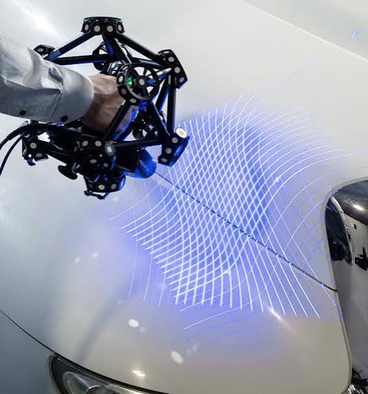
IMS can measure objects ranging from approximately one inch components to structures hundreds of feet in scale.
- Mechanical components
- Complex machined parts
- Tooling and fixtures
- Molds and patterns
- Machinery and equipment
- Automotive components and vehicles
- Aircraft components and structures
- Aerospace and space hardware
- Marine structures
- Industrial equipment
- Piping and mechanical systems
- Large assemblies
- Buildings and large structures
- Existing or legacy components without CAD
- Complex freeform surfaces
Surface condition does not automatically prevent an object from being scanned. IMS has experience working with shiny, dark, rusty, dirty and other challenging surfaces and selects the preparation and measurement strategy according to the application.
What Is 3D Laser Scanning Used For?
Dimensional Inspection
Compare measured geometry against nominal CAD, engineering requirements, datums and GD&T specifications.
Reverse Engineering
Capture existing geometry so components can be reconstructed as usable CAD when original design data is unavailable or incomplete.
Scan to CAD
Convert physical geometry into digital data that can be used to develop surface or solid CAD models.
CAD to Part Comparison
Overlay measured data with nominal CAD to identify dimensional variation and visualize deviations.
Tooling & Fixture Inspection
Measure tooling, fixtures and production equipment to evaluate condition, geometry, alignment and conformance to engineering requirements.
Part Fit Up & Interference Analysis
Digitally evaluate mating components and assemblies before physical installation to identify potential fit or interference conditions.
As Built Documentation
Capture the actual geometry of existing equipment, components or structures for engineering, modification and documentation.
Legacy Part Documentation
Digitize components that have incomplete, outdated or unavailable drawings and CAD data.
From Small Components to Large Structures
A small mechanical part and a structure hundreds of feet long may both be scanned, but they are not the same measurement problem.
For smaller applications, a metrology grade 3D scanner may provide the required geometry and dimensional performance directly.
As measurement volume increases, IMS can integrate additional metrology technologies to maintain dimensional control across the project.
This allows IMS to scale the measurement strategy to the application rather than relying on one piece of equipment for every job.

Controlled Large Volume 3D Scanning
Large structures require more than simply moving a scanner from one position to another.
As scanning progresses across a large measurement volume, registration and environmental effects can contribute to overall measurement uncertainty.
For accuracy sensitive large volume applications, IMS can establish a controlled coordinate network using a laser tracker.
Shared metrology nests allow an SMR measured by the laser tracker and a tooling ball measured by the 3D scanner to reference common control locations.
The laser tracker establishes large volume dimensional control while the scanner captures dense surface geometry.
This allows scanner data collected throughout the structure to be related back to a common controlled coordinate framework.
Large Volume Dimensional Control + Dense 3D Surface Capture
Laser Tracker + Photogrammetry + 3D Scanning
Certain projects require an even larger or more flexible reference network.
When appropriate, IMS can integrate GSI V STARS photogrammetry with the laser tracker control network and 3D scanning workflow.
Specialized reference locations can connect the photogrammetry network to the established control system while scanner targets provide additional references throughout the measurement area.
This approach can extend dimensional control across large or complex structures while allowing the scanner to capture detailed surface geometry as it moves through the project.
The exact combination of technologies is determined by the required accuracy, geometry, measurement volume, environment and project objective.
Integrated Measurement Framework
Measurement Uncertainty & Environmental Control
Scanner accuracy is only one part of measurement quality.
Actual measurement uncertainty is influenced by the equipment and measurement strategy being used as well as conditions such as:
- Measurement distance and volume
- Temperature
- Part temperature
- Humidity
- Surface condition
- Surface reflectivity and color
- Geometry
- Line of sight
- Equipment setup
- Reference network
- Registration strategy
IMS evaluates these factors when developing the measurement plan.
For large or accuracy sensitive projects, environmental conditions can be monitored throughout the measurement process and incorporated into the measurement strategy.
When appropriate, material specific coefficient of thermal expansion (CTE) can also be considered to account for dimensional changes associated with part temperature.
When a laser tracker control network is used, IMS can use the network and measurement conditions to help evaluate and manage measurement uncertainty across the project.
How Accurate Is IMS 3D Laser Scanning?
There is no responsible single accuracy number that applies to every 3D scanning project.
The achievable result depends on the equipment, object size, geometry, surface condition, measurement volume, environment, reference strategy and required deliverable.
For appropriate applications and controlled conditions, IMS has developed measurement strategies capable of approximately ±0.001 inch for localized measurements and approximately ±0.005 inch across measurement volumes approaching 100 feet.
These values should not be interpreted as guaranteed accuracy for every project. IMS reviews the required tolerance and application before recommending a measurement method and determining whether the requested measurement objective is technically appropriate.
For critical applications, the measurement strategy can include control network and environmental information to support evaluation of measurement uncertainty.
3D Scanning Equipment
Shining 3D FreeScan Trak Nova
The FreeScan Trak Nova provides portable 3D surface capture for dimensional inspection, reverse engineering and other metrology applications. Its tracking capability allows scanning without relying exclusively on traditional surface applied reference targets for appropriate applications.
Laser Tracker Integration
For large volume or accuracy sensitive applications, laser trackers can establish a controlled coordinate framework that supports the scanning process. IMS has experience with Leica and FARO laser tracker systems.
GSI V STARS Photogrammetry
For applications requiring large or distributed reference networks, GSI V STARS photogrammetry can be incorporated into the measurement strategy.
The equipment used is determined by the project rather than by a predetermined scanner only workflow.
From Scan Data to Engineering Deliverables
Raw scan data is rarely the final objective.
IMS can process, analyze and convert measurement data according to the customer's intended use.
Raw & Processed Data
- Raw measurement data, when applicable
- Registered scan data
- Point clouds
- Polygonal meshes
- Watertight mesh models
File Formats
- STL
- OBJ
- PLY
- 3MF
- STEP
- IGES
- SOLIDWORKS part files
- DXF
- Other project-specific formats
Inspection & Analysis
- Dimensional inspection reports
- CAD to part comparison
- Deviation / color maps
- Measurement coordinates
- Reverse engineered CAD
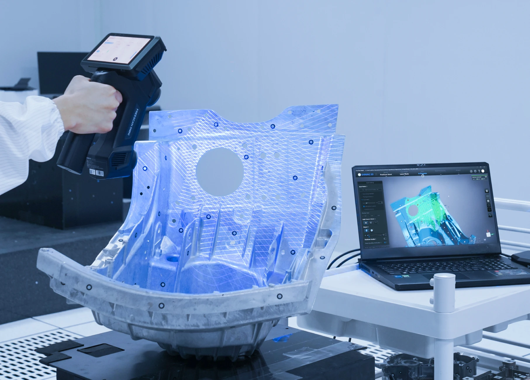
The appropriate deliverable is established before work begins so that data is collected and processed for its intended engineering use.
Professional Metrology & Engineering Software
IMS uses established metrology and engineering software to process, inspect, analyze and convert measurement data.
Different applications require different software workflows. Inspection, dimensional analysis and reverse engineering are treated as separate engineering tasks rather than interchangeable outputs from the scanner.
Our 3D Scanning Process
Understand the Requirement
We review the object, size, location, accuracy requirement, engineering objective, available CAD or drawings, surface condition and desired deliverable.
Develop the Measurement Strategy
IMS determines the appropriate scanner, reference strategy and supporting metrology equipment. For large or accuracy sensitive applications, this may include laser tracker control, photogrammetry, environmental monitoring or a combination of technologies.
Measure
The component, equipment or structure is scanned using the planned measurement strategy. Reference and environmental information is collected when required by the application.
Process & Validate
Scan data is registered, cleaned and evaluated. When control networks are used, the data can be related to the established coordinate framework and checked against appropriate control information.
Analyze or Model
Depending on the project, data can be used for dimensional inspection, CAD comparison, reverse engineering, fit up analysis, modeling or other engineering applications.
Deliver
IMS provides the agreed measurement data, reports, mesh, CAD or other engineering deliverable.
Mobile 3D Scanning Services
You do not necessarily need to ship large or sensitive equipment to a measurement laboratory.
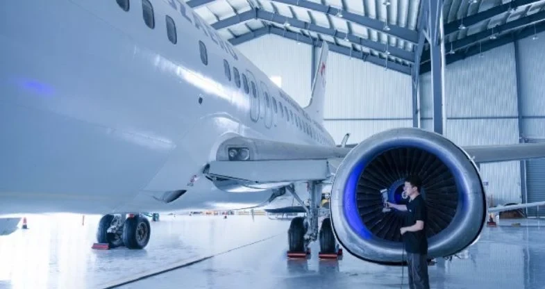
IMS specializes in portable metrology and can bring 3D scanning and supporting measurement equipment directly to the project.
Based in Rockledge on Florida's Space Coast, IMS supports projects throughout Florida and travels nationwide and internationally.
On site measurement is particularly valuable for:
- Large components
- Installed equipment
- Tooling and fixtures
- Aircraft and aerospace structures
- Machinery
- Sensitive equipment
- Large assemblies
- Objects that are impractical to transport
Industries We Support
IMS has 3D metrology experience across demanding engineering environments, including:
Why Innovative Measurement Solutions?
Measurement Strategy Before Equipment
We begin with the engineering requirement and select the measurement technology around the application.
Multiple Metrology Technologies
3D scanning can be combined with laser tracker measurement and photogrammetry when a project requires greater dimensional control or larger measurement volumes.
Engineering Focused Deliverables
IMS can take a project beyond raw scan data into inspection, analysis, reverse engineering and CAD deliverables.
Portable Measurement Capability
Projects can be performed directly at customer facilities throughout Florida, nationwide and internationally.
Experienced Metrology Professional
IMS is led by Zachary S. Ensley, whose professional metrology career began in 2010 and who holds the Coordinate Metrology Society credential Portable 3 D Metrologist, Level 1.
Contact IMS
Have a measurement challenge or upcoming project? Contact IMS to discuss the application, project requirements and appropriate measurement strategy.