

Precision Alignment Services
Precision Alignment Services
Know where it is. Determine where it needs to be. Move it with live metrology guidance. Verify the final position.
Innovative Measurement Solutions provides precision alignment for machinery, tooling, aerospace and space hardware, rails, piping, flanges and large assemblies using portable metrology and real time six degree of freedom measurement.
IMS can establish the required coordinate system, compare actual position with nominal, provide technicians with actionable movement or shim corrections, and continuously monitor the component as it is adjusted.
Based on Florida's Space Coast, IMS provides mobile precision alignment throughout Florida and supports projects nationwide and internationally.
Precision Alignment Driven by Measurement
Precision alignment is more than checking whether something is level.
A component may need to be positioned and oriented relative to engineering datums, CAD, a machine centerline, tooling monuments, another component, a building coordinate system or an established vehicle coordinate system.
IMS measures the actual condition, establishes the required nominal condition and calculates the difference between them.
During physical adjustment, IMS can provide live measurement feedback so mechanics, millwrights, technicians and assembly teams know how far and in what direction the component needs to move.
Once the adjustment is complete, IMS can remeasure the critical features and document the final alignment.
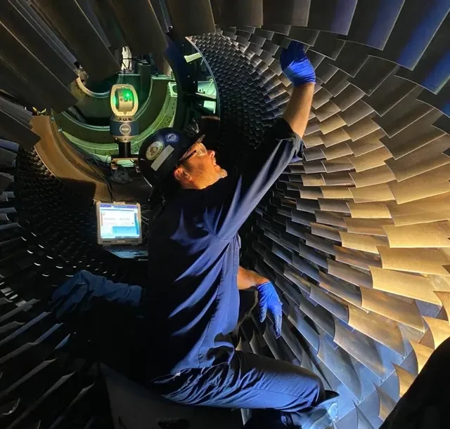
Six Degrees of Freedom: 6DOF Alignment
Many alignment problems require control of both position and orientation.
IMS can evaluate and guide movement in all six degrees of freedom:
This allows a component to be positioned not only in the correct location, but also at the required angular orientation.
For large or complex assemblies, live 6DOF feedback can significantly reduce trial and error adjustments.
Real Time Alignment Guidance
IMS can remain actively connected to the alignment process while technicians physically move the component.
Actual position is continuously compared with the required position so movement instructions can be updated as the assembly changes.
Depending on the project, guidance can include linear corrections, angular corrections, shim requirements, levelness, squareness or other project specific adjustments.
This creates a practical closed loop between metrology and the people performing the installation.
Precision Alignment Capabilities
Machinery Alignment
Support installation and alignment of motors, generators, pumps, gearboxes, machining equipment, machine rails, ways and other industrial machinery.
Aerospace & Space Hardware Alignment
Establish and control critical interfaces, datums, centerlines and component relationships during the positioning and assembly of large aerospace and space structures.
Large Assembly Alignment
Align large structural sections and subassemblies using controlled coordinate systems and live 6DOF feedback.
Tooling & Fixture Alignment
Set drill fixtures, assembly fixtures, build tooling, machine beds, jigs, tooling monuments and other production tooling.
Rail Alignment
Measure and align crane rails, CNC machine rails and other precision rail systems for position, straightness, level, parallelism and related geometric requirements.
Piping & Flange Alignment
Evaluate flange position, face angle, clocking, bolt patterns, centerlines, elevation, pipe routes and mating interfaces.
Bore & Boring Bar Alignment
Establish bore centerlines, evaluate coaxial relationships and support the setup or alignment of boring equipment.
Static Shaft & Coaxial Alignment
Evaluate static shaft geometry and coaxial relationships using measured geometric features.
Portable Machining Setup
Support positioning and alignment of portable gantry mills, boring systems and other temporary machining equipment.
Component & Part Assembly
Provide measured positioning and shim information when precision machined parts or assemblies must be brought into their required relationship.
Virtual Fit Up Before Physical Alignment
For complex installations, IMS can establish critical features, interfaces and datums before the final assembly operation begins.
A controlled reference network can be installed on the structure so the engineering coordinate system can later be re established.
When the mating component is ready for installation, IMS ties back into the established network, measures the component in its actual position and virtually compares that condition with the required nominal position.
The resulting difference can be translated into X, Y, Z, Rx, Ry and Rz corrections before and during physical movement.
This approach allows technicians to use measurement data to guide the installation rather than relying on repeated physical trial fitting.
Related service:
Virtual Fit Up & Assembly Verification →IMS can compare actual component position with nominal geometry before and during installation, reducing physical trial and error.
Rocket & Large Aerospace Assembly Experience
IMS leadership has extensive experience supporting precision alignment of large aerospace and space flight structures.
Experience includes aligning major rocket sections to one another, first stage structures to second stage structures, upper stages to payload fairings, multiple payload fairing assemblies, payload encapsulation activities, rocket engines and critical features on other space hardware.
Large components can exceed 25 feet in diameter and 100 feet in length.
Customer and program identities remain confidential unless publication is specifically authorized.

Engine & Critical Interface Alignment
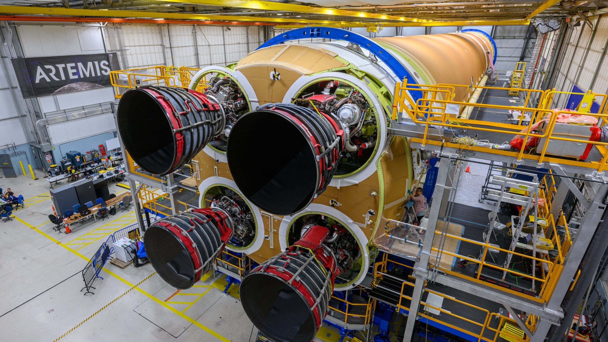
Engine installation can require multiple engineering relationships to be controlled simultaneously.
IMS can establish centerlines, axes, mounting interfaces, flanges, datums and other critical features before installation.
For applicable rocket engine alignment work, the engine position can be evaluated relative to the vehicle centerline and required mounting geometry.
Previously established control features allow the coordinate system to be recovered during installation.
The engine can then be measured in its actual position, virtually compared with nominal and guided into the required location and orientation.
Shim Calculations & Adjustment Guidance
Some alignment problems are best corrected through controlled shimming rather than simple translation.
IMS can use measured geometry to calculate shim requirements for machinery, tooling and precision assemblies.
Shim information can help technicians maintain required levelness, squareness, orientation or interface relationships while the component is being positioned.
After adjustments are made, IMS can remeasure the system to verify the resulting condition.
Piping, Flange & Interface Alignment
IMS can measure and evaluate piping and flange geometry including:
- Flange position
- Flange face orientation
- Clocking
- Bolt hole pattern
- Pipe centerline
- Elevation
- Pipe route
- Mating interface
- Relationship to surrounding equipment or facility coordinates
These measurements can determine whether existing or fabricated components are positioned and built appropriately for the intended interface.
IMS can also capture existing interfaces to support as built modeling, fabrication verification and fit up planning.
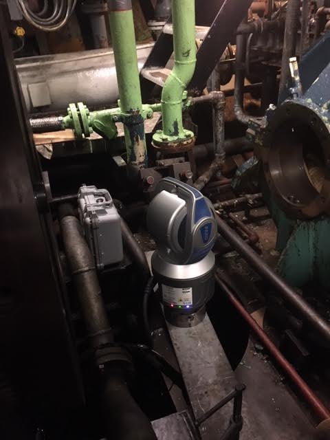
Geometric Alignment & Machine Geometry
IMS can evaluate and establish geometric conditions including:
- Level
- Plumb
- Straightness
- Flatness
- Squareness
- Parallelism
- Perpendicularity
- Centerline
- Coaxiality
- Position
- Angular orientation
The required geometry is evaluated within the engineering coordinate system or reference framework appropriate to the project.
Alignment to CAD, Datums or Physical References
The alignment reference should come from the engineering requirement.
IMS can establish alignment from CAD geometry, drawing datums, vehicle coordinate systems, machine centerlines, building coordinates, tooling points, monuments, existing equipment or another physical component.
When a reliable coordinate system does not already exist, IMS can evaluate the available geometry and establish or recommend a practical reference strategy.
This is especially important on legacy equipment, large installations and field projects where the original reference system may be incomplete or inaccessible.
Alignment Strategies Built Around the Actual Problem
Precision alignment rarely happens under perfect conditions.
Every project presents a different combination of geometry, tolerance, access, environmental conditions, coordinate systems, tooling and installation constraints.
IMS does not rely on one alignment procedure or one measurement technology for every application.
Drawing on broad metrology experience across aerospace, space, defense, manufacturing, marine, nuclear, energy and other demanding environments, IMS develops the measurement strategy around the actual problem.
When conventional references are unavailable, IMS can establish practical coordinate systems from engineering datums, physical geometry, tooling points, monuments, centerlines, CAD or other reliable references.
When one measurement technology is not sufficient, multiple portable metrology technologies can be combined when appropriate.
The objective remains the same: establish where the component is, determine where it needs to be, provide actionable corrections and verify the final alignment.
Measurement Technologies
Equipment selection depends on the required tolerance, geometry, measurement volume, access, environment and customer requirements.
Depending on the project, IMS can incorporate:
- Laser trackers
- SMRs
- T Probes
- Tooling balls and control nests
- Hidden point and vector tooling
- 3D laser scanning
- Photogrammetry
- Total stations
- Precision leveling methods
- Hybrid measurement networks
Controlled Measurement Networks
Large alignment projects often require the coordinate system to remain stable across multiple instrument positions, work areas or stages of assembly.
IMS can establish controlled measurement networks that provide a common reference framework throughout the alignment volume.
Control points can be periodically remeasured to evaluate network stability and identify movement during the alignment process.
This is particularly valuable when large assemblies must be moved, disconnected, reconfigured or measured over an extended period.
Environmental Monitoring, Drift & Thermal Effects
Large components and precision assemblies can move as environmental conditions change.
For critical alignment work, IMS can monitor relevant environmental and material conditions, evaluate drift and apply coefficient of thermal expansion considerations when appropriate.
Control points on the component and surrounding reference environment can help distinguish component movement from changes within the measurement environment.
The exact environmental strategy depends on the required tolerance, material, measurement volume and project conditions.
Alignment Accuracy & Measurement Uncertainty
There is no responsible universal accuracy value for every alignment project.
IMS has experience supporting extremely tight alignment requirements, but achievable measurement uncertainty depends on the instrument, geometry, measurement volume, environment, reference network and alignment methodology.
Critical requirements are reviewed before the project so the proposed measurement strategy can be evaluated against the required tolerance.
For appropriate applications, network and environmental information can also support measurement uncertainty evaluation.
Before, During & After Alignment Verification
Initial position establishes the starting condition
Live measurement feedback provides actionable corrections
Critical features remeasured to verify achieved position
IMS can document the alignment condition throughout the process.
Before movement, the initial position establishes the starting condition.
During adjustment, live measurement feedback provides actionable corrections.
After adjustment, critical features can be remeasured to verify the achieved position and orientation.
This gives the customer objective measurement data showing the final condition rather than relying only on the fact that the physical installation was completed.
Alignment Deliverables
Depending on customer requirements, deliverables can include:
- Initial / before condition
- Final / after condition
- X, Y and Z corrections
- Rx, Ry and Rz angular corrections
- 6DOF alignment results
- Shim maps and shim recommendations
- Alignment reports
- CAD comparison
- Feature and coordinate data
- Screenshots and visual reports
- Raw measurement data when appropriate
- Final verification / acceptance results
- Customer specific reporting formats
Our Precision Alignment Process
Define the Engineering Requirement
Review CAD, drawings, datums, tolerances, interfaces, installation constraints and the required final condition.
Evaluate the Physical Situation
Assess access, geometry, movement capability, environmental conditions, measurement volume and available references.
Establish the Coordinate System
Use engineering datums, CAD, tooling points, monuments, centerlines, existing equipment or an appropriate project specific reference framework.
Measure the Actual Condition
Capture the component's current position and orientation.
Compare Actual to Nominal
Calculate the required positional and angular corrections.
Guide the Adjustment
Provide live feedback, 6DOF corrections and shim information while technicians move or adjust the component.
Verify the Final Position
Remeasure critical features and document the achieved alignment.
Report
Provide the agreed alignment data, visualizations and final results.
Mobile Precision Alignment Services
Alignment normally has to happen where the equipment or structure is installed.
IMS brings portable metrology directly to the customer's facility, assembly area, machine installation or field location.
Based in Rockledge on Florida's Space Coast, IMS provides on site precision alignment throughout Florida and travels nationwide and internationally.
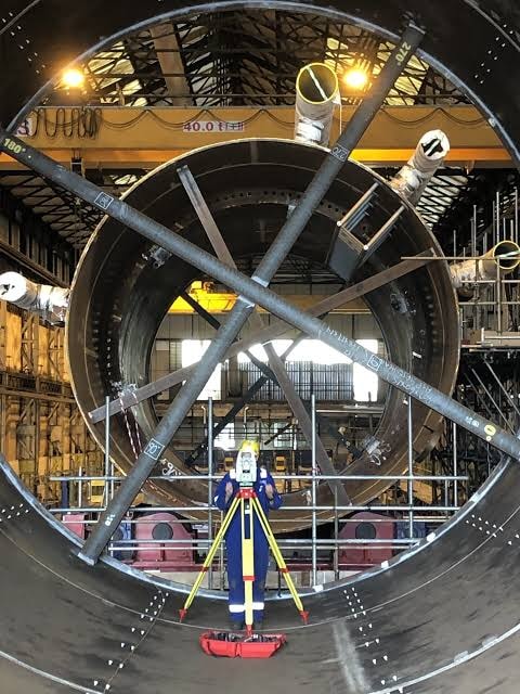
Industries We Support
IMS has precision alignment and metrology experience across:
Why Innovative Measurement Solutions?
Real Time 6DOF Guidance
IMS can translate measured conditions into live X, Y, Z, Rx, Ry and Rz corrections while technicians physically adjust the component.
Adaptable Alignment Strategy
The measurement approach is developed around the actual geometry, tolerances, access, references and environment rather than a fixed procedure.
Large Volume Metrology
Controlled laser tracker networks, photogrammetry and other portable technologies allow alignment to scale to very large structures.
Virtual Fit Up
Actual component position can be compared with nominal geometry before and during installation, reducing physical trial and error.
Coordinate System Expertise
IMS can work from established engineering references or develop an appropriate reference strategy when the existing coordinate system is incomplete.
Shim & Adjustment Calculations
Measurement data can be translated into practical movement and shim information for mechanics, millwrights and assembly teams.
Environmental Awareness
Critical alignments can incorporate drift monitoring, temperature measurement, CTE considerations and controlled reference networks.
Final Verification
IMS can remeasure the completed installation and document the achieved condition.
Experienced Metrology Professional
IMS is led by Zachary S. Ensley, whose professional metrology career began in 2010 and who holds the Coordinate Metrology Society credential Portable 3 D Metrologist, Level 1.