

REVERSE ENGINEERING
Reverse Engineering Services
Transform physical parts, assemblies and structures into accurate, usable CAD models and engineering drawings.
Innovative Measurement Solutions combines precision 3D measurement, 3D laser scanning and professional CAD software to reverse engineer components ranging from small parts to large industrial and aerospace structures.
Whether the original CAD was lost, drawings no longer exist, a component is obsolete, or an accurate as built model is needed, IMS can develop the digital engineering data required for your next step.
Based on Florida's Space Coast, IMS provides mobile reverse engineering services throughout Florida and supports projects nationwide and internationally.
Metrology Driven Reverse Engineering
Reverse engineering is more than creating a surface that follows scan data.
The physical component must first be measured accurately. The geometry must then be interpreted according to the purpose of the project and reconstructed into useful engineering data.
IMS combines metrology and CAD expertise throughout this process.
Depending on the application, IMS can use 3D laser scanning, laser tracker measurement, photogrammetry or a hybrid measurement strategy to capture the physical geometry.
That measurement data becomes the foundation for developing an as built model, design intent model, manufacturing ready CAD model, engineering drawing or other required deliverable.
The objective is not simply to digitize the part. It is to create engineering data that is useful for what comes next.
Reverse Engineering Capabilities
Machined Components
Reconstruct manufactured features, interfaces, bores, holes, planes, radii and other mechanical geometry into usable CAD.
Cast & Molded Components
Capture complex surfaces and reconstruct combinations of freeform and geometric features.
Tooling & Fixtures
Digitize existing manufacturing tooling, drill fixtures, assembly fixtures and build tooling for documentation, reproduction or modification.
Aerospace Components & Structures
Capture complex aerospace geometry, tooling, assemblies, aircraft structures and related components.
Machinery & Industrial Equipment
Create as built CAD and engineering documentation for existing machinery, equipment and installations.
Piping & Facility Geometry
Capture existing piping, flanges, equipment interfaces and surrounding geometry for modification, replacement and fit up planning.
Sheet Metal & Fabricated Components
Reconstruct fabricated geometry, interfaces and assemblies from the physical component.
Obsolete & Legacy Parts
Create new CAD and drawings when original engineering data is unavailable.
Buildings & Large Structures
Use large volume metrology to capture existing structures and convert physical geometry into usable digital information.
Statues & Historical Artifacts
Digitize complex physical geometry for documentation, preservation, replication planning or other appropriate applications.
From Physical Part to Digital Engineering Data
A reverse engineering project often begins with very little information.
The customer may have a physical component and nothing else: no CAD, no drawing and no original manufacturer data.
IMS can begin directly from the physical component.
The part is evaluated to determine its size, geometry, accessibility, surface characteristics and intended use. From there, IMS determines an appropriate measurement and modeling strategy.
The resulting data can then be developed into CAD models, meshes, assemblies, drawings or other engineering deliverables.
As Built vs. Design Intent
One of the most important decisions in reverse engineering is determining what the finished CAD model is supposed to represent.
A physical component is rarely geometrically perfect. Manufacturing variation, wear, deformation, damage, corrosion and previous modifications can all influence the measured surface.
IMS discusses the intended use of the model before CAD reconstruction begins.
As Built CAD
An as built model represents the component substantially as it physically exists at the time of measurement. This approach is useful when the objective is to document existing geometry, interfaces, installed conditions or actual manufactured shape.
Design Intent CAD
A design intent model reconstructs the geometry the component was likely intended to have.
Rather than reproducing every small measured variation, IMS evaluates geometric relationships such as:
- Planarity
- Cylindrical features
- Concentricity
- Symmetry
- Parallel and perpendicular relationships
- Nominal radii
- Repeated features
- Surrounding geometry
- Mating interfaces
The resulting CAD can represent cleaner engineering geometry while remaining grounded in the physical measurement data.
Manufacturing Ready CAD
When the objective is replacement or future manufacturing, IMS can develop clean CAD geometry appropriate for downstream manufacturing based on the agreed project requirements. Optional 2D manufacturing drawings can then define the geometry for the customer's selected manufacturer.
Reverse Engineering Worn, Damaged or Corroded Parts
Sometimes copying the measured surface exactly would reproduce the problem.
A legacy component may be:
- Worn
- Damaged
- Corroded
- Bent
- Previously repaired
- Modified
- Partially missing
IMS can evaluate the remaining geometry and use available engineering relationships to reconstruct appropriate geometry where the project requires it.
Information may come from:
- Symmetry
- Undamaged areas
- Surrounding geometry
- Mating components
- Repeated features
- Existing drawings
- Known interfaces
- Assembly relationships
- Customer provided engineering information
Measured geometry and reconstructed or inferred geometry should be clearly distinguished when that distinction is important to the project.
Reverse Engineering Obsolete & Unavailable Parts
When an original manufacturer no longer supports a component, the physical part itself may become the best source of dimensional information.
IMS can capture the existing component and develop CAD and engineering drawings that can support the customer's replacement part process.
This can be particularly valuable when:
- Original CAD has been lost
- Drawings are unavailable
- The manufacturer no longer exists
- Replacement parts are discontinued
- Legacy equipment must remain operational
- Existing drawings do not represent the current configuration
- A replacement must interface with existing equipment
IMS provides the measurement, CAD and inspection services.
IMS does not manufacture the replacement component.
The customer can provide the resulting engineering data to the manufacturer or machine shop of their choice.
Complex Surface Reverse Engineering
Not every component can be reconstructed using simple planes, cylinders and holes.
IMS has experience with complex and freeform geometry including:
- Aircraft surfaces
- Aerodynamic geometry
- Castings
- Molded components
- Organic surfaces
- Sculpted geometry
- Complex transitions
- Irregular structures
Dense 3D scan data can be used as the geometric foundation while professional reverse engineering software is used to reconstruct appropriate CAD surfaces and solid geometry.
The modeling strategy depends on whether the customer requires an as built representation, design intent geometry or another defined output.
Reverse Engineering Assemblies
Reverse engineering does not have to stop at an individual component.
IMS can capture multiple components while maintaining their spatial relationships within a common coordinate system.
This can support:
- Assembly documentation
- Interface definition
- Replacement component development
- Modification planning
- Fit up analysis
- Clearance evaluation
- Interference detection
CAD assemblies can then be evaluated for potential geometric clashes between components or surrounding structures.
Large Scale Reverse Engineering
Reverse engineering can extend far beyond tabletop components.
For large assemblies and structures, IMS can combine laser tracker measurement, 3D scanning and photogrammetry within a controlled measurement network.
The laser tracker can establish large volume dimensional control while the scanner captures dense surface geometry.
Photogrammetry can be incorporated when appropriate to extend or reinforce the measurement network.
IMS has applied this type of hybrid methodology to complex large scale structures, including an aircraft engine test stand.
This allows detailed geometry to be captured while maintaining a controlled coordinate framework across a much larger measurement volume.

CAD Reconstruction & Design Intent
Scan data represents what the measurement system observed.
Engineering CAD requires interpretation.
During reconstruction, IMS evaluates relationships between physical features to determine the appropriate modeling approach.
For example, a measured cylindrical feature contains normal manufacturing variation and measurement variation. The CAD model may need to represent the intended cylinder rather than every microscopic variation in the measured surface.
The same principle applies to planes, axes, radii, symmetric features, interfaces and other engineered geometry.
This is one of the key differences between automatically surfacing scan data and reconstructing useful engineering CAD.
CAD to Scan Verification
Creating the CAD model is not the final step.
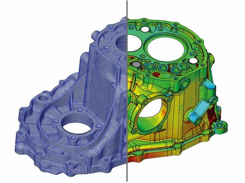
IMS can compare the reconstructed CAD directly back to the original measurement data.
A deviation analysis can identify where the CAD model differs from the measured physical geometry.
Color maps provide an intuitive visual representation of these differences across the component.
This verification process can be used to refine the model and evaluate whether the reconstructed geometry appropriately represents the physical measurement data according to the intended modeling strategy.

CAD & Engineering Deliverables
Depending on project requirements, IMS can provide:
- Parametric solid models
- Feature based CAD models
- Surface models
- As built CAD
- Design intent CAD
- Manufacturing oriented CAD models
- Assembly models
- Polygonal meshes
- STL models
- 2D engineering drawings
- 3D engineering documentation
- CAD to scan deviation reports
- Color map verification
- Assembly visualizations
- Assembly animations
- Interference/clash analysis
- Raw measurement data when appropriate
The required deliverables should be established at the beginning of the project so the measurement and modeling strategy supports the customer's intended use.
2D Manufacturing Drawings
A CAD model alone may not provide all of the information needed to manufacture or inspect a component.
IMS can develop 2D engineering drawings from reconstructed CAD.
Depending on project scope, drawings can include:
- Dimensions
- GD&T
- Datum structures
- Feature callouts
- Notes
- Views and sections
- Detail views
- Title blocks
- Material or customer provided engineering information
- Other manufacturing requirements provided or established within the project scope
This allows the reverse engineering project to produce both digital geometry and conventional engineering documentation.
Common CAD File Formats
IMS can work with and deliver a wide range of native and neutral engineering formats depending on the software and project requirements.
Common formats include:
- STEP
- IGES
- Parasolid
- SOLIDWORKS
- CATIA
- Fusion 360 compatible formats
- STL
- 3MF
- DXF
- Other appropriate native or neutral CAD formats
The required deliverable format should be identified before modeling begins whenever possible.
Professional Reverse Engineering Software
No single software package is ideal for every geometry.
IMS uses multiple professional metrology and CAD platforms and can move between software packages when their specialized tools provide a better workflow for a particular component.
Software experience includes:
This flexibility allows the modeling workflow to be selected around the geometry rather than forcing every project through one software platform.
Small Parts to Large Structures
IMS can reverse engineer components ranging from small parts to structures hundreds of feet in size.
However, physical size alone does not determine whether a project is feasible.
Important factors include:
- Feature size
- Internal geometry
- Accessibility
- Required tolerance
- Surface condition
- Geometry complexity
- Measurement technology
- Required deliverable
Very small components with complex inaccessible internal features may require measurement technology outside the practical capability of the available system.
IMS evaluates feasibility before committing to the project rather than promising that every physical geometry can be captured accurately.
Closed Loop Replacement Part Workflow
IMS can support more than the initial reverse engineering process.
Measure the Existing Component
Capture the physical geometry using the appropriate metrology technology.
Reconstruct the CAD
Develop the agreed as built or design intent model.
Verify the CAD
Compare the reconstructed model back against the measurement data.
Create Manufacturing Drawings
Develop 2D engineering documentation when included in the project scope.
Customer Selects a Manufacturer
The customer provides the CAD and drawings to the manufacturer or machine shop of their choice.
IMS Inspects the Replacement
After manufacturing, IMS can dimensionally inspect the replacement component against the CAD and engineering drawing.
This creates a closed measurement loop from the original physical component through final dimensional verification.
Our Reverse Engineering Process
Understand the Objective
IMS begins by determining what the customer intends to do with the final data. Is the goal documentation, reproduction, modification, manufacturing, inspection, fit up or something else?
Evaluate the Physical Component
The component is reviewed for size, geometry, accessibility, surface condition, complexity and required dimensional fidelity. IMS determines whether the project is feasible and which measurement technology is appropriate.
Define the Modeling Strategy
The customer and IMS establish whether the required result is an as built model, design intent model, manufacturing oriented model or another defined deliverable.
Capture the Geometry
IMS uses the appropriate combination of 3D scanning, laser tracker measurement, photogrammetry or other metrology methods.
Reconstruct the CAD
Measurement data is processed and reconstructed using professional reverse engineering and CAD software.
Verify the Model
The completed CAD can be compared against the original measurement data using dimensional deviation analysis and color mapping.
Create Additional Engineering Deliverables
2D drawings, assemblies, visualizations, animations or other agreed deliverables are developed when included in the project scope.
Support Final Inspection
If a replacement component is manufactured, IMS can inspect the new component against the reconstructed engineering definition.
Mobile Reverse Engineering Services
Large equipment and structures do not always need to be transported to IMS.
Portable metrology allows IMS to capture physical geometry directly at the customer's facility.
Based in Rockledge on Florida's Space Coast, IMS provides mobile reverse engineering throughout Florida and travels nationwide and internationally.
Industries We Support
IMS has reverse engineering and metrology experience across:
Why Innovative Measurement Solutions?
Metrology + CAD
IMS combines precision measurement with reverse engineering and CAD rather than treating scanning and modeling as unrelated processes.
Design Intent Matters
The modeling strategy begins with understanding whether the customer needs the physical condition reproduced or the intended engineering geometry reconstructed.
Multiple Measurement Technologies
3D scanning, laser trackers and photogrammetry can be used individually or together according to the scale and requirements of the project.
Complex Surface Capability
IMS can reconstruct both traditional mechanical geometry and complex freeform surfaces.
CAD Verification
Reconstructed CAD can be compared directly against the original measurement data to evaluate geometric agreement.
Manufacturing Documentation
Optional 2D drawings can extend the project from a digital model to conventional engineering documentation.
Closed Loop Verification
IMS can return after a replacement component is manufactured and inspect it against the reconstructed engineering definition.
Experienced Metrology Professional
IMS is led by Zachary S. Ensley, whose professional metrology career began in 2010 and who holds the Coordinate Metrology Society credential Portable 3D Metrologist, Level 1.