
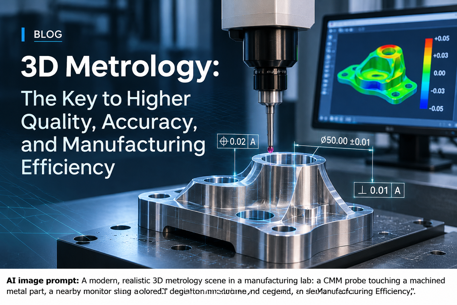
3D metrology is the practice of measuring physical objects in three dimensions and comparing those measurements against an engineering requirement. In manufacturing, that requirement is typically a CAD model, an engineering drawing, a GD&T callout, or a defined coordinate system.
The goal is not to collect data for its own sake. The goal is to answer a specific engineering question: does this part, tool, or assembly meet its dimensional requirements, and if not, where does it deviate and by how much?
What 3D Metrology Measures in Modern Manufacturing
Coordinate measurement establishes the position of physical features in three-dimensional space. From those coordinates, engineers can evaluate dimensions, angles, distances, surface profiles, and geometric relationships between features.
In practice, this means measuring hole locations, flange interfaces, surface profiles, assembly datums, bore diameters, flatness, perpendicularity, and hundreds of other characteristics depending on the component and its engineering requirements.
Surface geometry is particularly important for complex parts. A single measured point tells you where one location is. Dense surface data tells you how the entire surface behaves — whether it is bowed, twisted, tapered, or otherwise deviating from nominal in a way that isolated point measurements would not reveal.
Dimensional tolerances define the acceptable range for each characteristic. Metrology establishes whether the physical part falls within that range. When it does not, the measurement data provides the information engineering and manufacturing teams need to evaluate the deviation and decide how to respond.
How Manufacturers Apply 3D Measurement
Aerospace suppliers use 3D metrology to verify large structural assemblies, confirm tooling geometry, and document component interfaces before integration. A wing spar, fuselage section, or engine mount involves dozens of critical dimensional relationships that must be verified before the next assembly step.
Precision machining shops use dimensional inspection to confirm that finished components meet drawing requirements. First article inspection verifies that a new part program produces geometry within tolerance before production continues. In-process inspection identifies deviations while the part is still on the machine and correction is practical.
Production tooling — jigs, fixtures, and assembly tools — must also be verified. Tooling that has shifted, settled, or worn can introduce dimensional variation into every part it produces. Periodic tooling inspection catches those conditions before they affect production output.
Industrial equipment installations require alignment and position verification. Machinery that is not positioned correctly relative to its mating components or reference coordinate system can create operational problems that are difficult to diagnose without measurement data.
Laser Trackers, 3D Scanners, and Portable Measurement Systems
Different measurement technologies are suited to different applications. Selecting the right tool depends on the required tolerance, the size of the component, the geometry being measured, and the type of result the project requires.
Laser tracker measurement is well suited to large-volume coordinate measurement. A laser tracker measures the position of a retroreflector target in three dimensions with high accuracy across distances that can extend to tens of meters. Applications include large assembly measurement, tooling verification, machinery alignment, datum establishment, and precision positioning. When a project requires accurate coordinate data across a large component or structure, a laser tracker is often the appropriate choice.
3D laser scanning captures dense surface geometry. Instead of measuring selected points, a scanner collects thousands or millions of surface points that together describe the actual shape of the component. This is valuable for CAD-to-part comparison, reverse engineering, surface inspection, and applications where the distribution of deviation across a surface matters as much as individual feature measurements. A color deviation map generated from scan data can show at a glance where a surface is within tolerance and where it is not.
Industrial photogrammetry uses calibrated cameras and coded targets to establish accurate coordinate networks across large structures. It is particularly useful when line of sight is limited, when a large number of reference points must be established simultaneously, or when a portable, non-contact measurement approach is needed for large-scale work.
Portable coordinate measuring arms and other handheld systems are used for smaller components where flexibility and access matter more than extended measurement range. These systems are common in machine shops and production environments where parts move through multiple inspection steps.
Comparing Physical Parts Against CAD Models
CAD comparison is one of the most common deliverables in modern dimensional inspection. The process involves aligning measured data — whether discrete points or a dense point cloud — with the nominal CAD geometry and calculating the deviation at each measured location.
The alignment method matters. Depending on the engineering requirement, the data may be aligned to defined datums, physical features, customer-specified coordinate systems, or a best-fit calculation. Using the wrong alignment can produce results that appear to show a problem where none exists, or miss a real deviation because the reference frame is incorrect.
Once aligned, the inspection software calculates the distance between each measured point and the nearest nominal surface. Those deviations are reported as individual measurements, GD&T results, or a color deviation map depending on what the project requires.
GD&T evaluation requires understanding the tolerance type, the datum reference frame, and the applicable standard. Flatness, perpendicularity, true position, profile of a surface, and other GD&T callouts each have specific evaluation methods. The inspection report should reflect those requirements rather than substituting a simpler measurement that does not address the actual engineering specification.
Dimensional inspection reports document the measured values, the nominal values, the tolerances, and the pass or fail status for each characteristic. For first article inspection, those reports may need to follow a specific format such as AS9102 or a customer-defined template.
What Manufacturers Need to Know About Measurement Accuracy
Measurement accuracy is not a fixed property of an instrument. It depends on the complete measurement process — the equipment, the environment, the reference strategy, the measurement method, and the analysis approach.
Calibration establishes that an instrument performs within its specified limits under controlled conditions. It does not automatically make every measurement result traceable or fit for a specific tolerance. Metrological traceability requires an unbroken chain of calibrations connecting the measurement result back to a national or international standard, with each step contributing to the overall measurement uncertainty.
Measurement uncertainty quantifies the range within which the true value is expected to fall. For measurements near a tolerance limit, uncertainty matters. A result that appears to be within tolerance may actually be outside it once measurement uncertainty is considered, and vice versa. ISO 14253-1 addresses how conformity and nonconformity decisions should account for measurement uncertainty.
Environmental conditions affect measurement results in ways that are easy to underestimate. Temperature changes cause materials to expand and contract. A steel component measured at 65°F will have different dimensions than the same component measured at 85°F. For tight-tolerance work, temperature compensation or controlled measurement conditions may be necessary.
Repeatability — the ability to obtain consistent results from repeated measurements of the same characteristic — is a basic requirement for any reliable inspection process. A measurement that produces different results each time it is taken cannot support a confident engineering decision.
The Role of 3D Metrology in 2026
Portable measurement systems have made it practical to bring accurate dimensional inspection directly to large structures, field installations, and production environments that cannot be moved to a fixed inspection laboratory. That shift has expanded where and when measurement can be applied in the manufacturing process.
Digital inspection workflows allow measurement data to be processed, analyzed, and reported more efficiently than paper-based processes. Inspection results can be linked to CAD geometry, shared with engineering teams, and archived for traceability. When a deviation is identified, the data is available immediately rather than waiting for a report to be compiled after the fact.
Automated data collection is increasing in high-volume production environments. Robotic scanning systems and integrated measurement cells can inspect components at production rates that manual inspection cannot match. These systems are most effective when the inspection strategy — the measurement method, alignment approach, and acceptance criteria — has been carefully defined in advance.
Integration with manufacturing systems allows inspection data to feed directly into production decisions. When measurement results are connected to the process that produced the part, engineering and manufacturing teams can identify patterns, track trends, and respond to dimensional variation before it becomes a production problem.
How Innovative Measurement Solutions Supports Complex Measurement Projects
Innovative Measurement Solutions is a portable metrology company based in Rockledge, Florida. IMS supports projects throughout Florida, nationwide, and internationally.
IMS services include 3D laser scanning, laser tracker measurement, dimensional inspection, reverse engineering, precision alignment, industrial photogrammetry, and tooling and fixture verification.
IMS works across aerospace and space, aviation, defense, naval and marine, nuclear and power generation, industrial manufacturing, oil and gas, and engineering and construction applications. The company brings portable measurement equipment to the project location rather than requiring customers to ship components to a fixed facility.
The measurement strategy for each project is developed around the engineering requirement, the component geometry, the required tolerance, and the deliverable the customer needs after the work is complete.
Choosing a Measurement Approach
Before requesting metrology services, it helps to have the following information available: engineering drawings or CAD files, required tolerances or GD&T callouts, part dimensions and measurement volume, project location, access conditions, and the specific deliverable you need — whether that is a dimensional report, a CAD comparison, an alignment result, or something else.
The more clearly the engineering question is defined before measurement begins, the more directly the inspection strategy can be built around answering it. A measurement performed without a clear engineering requirement may collect data that does not address the actual decision the project depends on.
If you have a measurement project and want to discuss the approach, contact IMS to describe the application, the component, and the result you need.