
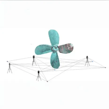
Measurement becomes more complex as the working volume grows. A bench-scale CMM operates in a controlled environment with a rigid structure, a defined temperature, and a short measurement range. Large-scale metrology — measuring structures, assemblies, and components across working volumes of several meters to tens of meters or more — introduces a different set of engineering challenges.
The instrument is only one part of the problem. Thermal expansion, structural deflection under gravity, reference network design, measurement geometry, and coordinate system strategy all contribute to the final measurement result. Understanding these factors is what separates a measurement that produces defensible data from one that produces numbers without context.
What Is Large-Scale Metrology?
Large-scale metrology — also called large-volume metrology — refers to dimensional measurement of objects and assemblies whose size makes conventional fixed CMM measurement impractical or impossible. Working volumes typically range from a few meters to tens of meters, and in some applications beyond that.
Typical applications include aerospace structural assemblies, aircraft tooling and fixtures, large machined components, shipbuilding and marine structures, industrial machinery installation and alignment, and spaceflight hardware. The common thread is that the engineering requirement demands dimensional control across a volume that cannot be brought to a fixed measurement machine.
The instruments used for large-scale work — laser trackers, industrial photogrammetry systems, and 3D laser scanners — are portable and can be brought to the component or structure. Each has a different capability profile, and the choice of technology should be driven by the engineering requirement.
Why Large Measurements Become More Difficult
Several categories of error grow with measurement volume. Some are physical — thermal expansion, structural deflection. Some are geometric — the relationship between instrument position, target location, and measurement angle. Some are systematic — how a reference network is designed and how multiple instrument positions are combined.
None of these factors disappear at smaller scales, but at bench scale they are often small enough to be managed by the measurement environment itself. At large scale, they must be explicitly understood and addressed in the measurement plan.
Thermal Expansion: The ΔL = α × L × ΔT Relationship
All materials expand and contract with temperature. The relationship is described by:
ΔL = α × L × ΔT
Where ΔL is the dimensional change, α is the coefficient of thermal expansion (CTE) of the material, L is the nominal length, and ΔT is the temperature change from the reference temperature.
For common structural steels, CTE is approximately 11–12 µm/m·°C, though the exact value varies by alloy. Using a nominal value of 12 µm/m·°C as an illustrative example: a 10-meter steel structure that is 5°C above the reference temperature has expanded by approximately 0.60 mm relative to its nominal dimension at the reference temperature. At 10°C above reference, that becomes approximately 1.20 mm. These are not small numbers when tolerances are tight.
Metrology software can apply a temperature correction when the material CTE and component temperature are known. This correction reduces the thermal contribution to the measurement result, but it does not eliminate it. The correction is only as accurate as the temperature data available, and real components in real environments are rarely at a perfectly uniform temperature.
Temperature Gradients Are a Different Problem
Uniform temperature change — where the entire component is at a consistent temperature above or below the reference — is the case that thermal correction handles most directly. Temperature gradients are more complex.
When one part of a structure is warmer than another, the structure does not simply grow uniformly — it deforms. A temperature gradient across a large beam or frame can introduce bowing, twisting, or differential expansion between features that are being measured relative to each other. Software correction based on a single measured temperature cannot fully account for this, because the gradient itself is not uniform.
For critical large-volume measurements, the practical response is to work in a thermally stable environment where possible, allow the component to reach thermal equilibrium before measuring, and document the measurement temperature. When thermal stability cannot be achieved, the thermal contribution to measurement uncertainty should be explicitly evaluated and reported rather than assumed away.
Gravity and Structural Deflection
Large structures deflect under their own weight. The magnitude of that deflection depends on the material, the geometry, the support conditions, and the orientation of the component during measurement.
A component measured horizontally on a support fixture may not have the same geometry when it is installed vertically, cantilevered, or supported at different points. This is not a measurement error in the conventional sense — the measurement may be entirely correct for the condition in which it was taken. The question is whether that condition matches the functional condition the engineering requirement is based on.
For large-scale work, the measurement plan should consider the support and orientation of the component during measurement relative to its functional condition. When the two differ significantly, the deflection difference may need to be accounted for in the analysis. This is an engineering judgment that belongs in the measurement plan, not something that can be corrected after the fact by software alone.
Coordinate Systems and Datum Strategy
A technically precise measurement in the wrong coordinate framework can still be unusable. The coordinate system used to report measurement results determines what the data means relative to the engineering requirement.
For large-scale work, the coordinate system must be defined around the engineering datums — the reference features, planes, axes, or points that the drawing or CAD model uses to define the part. Measuring accurately in an arbitrary coordinate system and then trying to transform the data into the correct framework introduces additional uncertainty and can obscure systematic errors.
Establishing the correct coordinate system is part of the measurement plan, not an afterthought. The IMS article on why coordinate systems matter in laser tracker measurement covers this in detail, including how datum selection affects the interpretation of measurement results and how errors in the coordinate system propagate through the data.
Reference Networks and Multiple Instrument Positions
Many large-volume measurement projects cannot be completed from a single instrument position. The structure may be too large, features may be obstructed, or the working volume may exceed the practical range for the required accuracy. When multiple positions are needed, a controlled reference network maintains a common coordinate framework across all setups.
A reference network consists of stable, well-distributed control points — typically precision tooling balls, monuments, or nests — that are measured from each instrument position. The measured positions of those control points allow data from each setup to be combined in a single coordinate system. The quality of that combination depends directly on the quality of the reference network.
Reference points should be distributed to provide good geometric coverage of the working volume. They should be placed where they will remain stable throughout the measurement — not on surfaces that will move, flex, or be disturbed by the work being done. Sufficient redundancy allows errors to be detected and managed. A poorly designed or poorly measured reference network introduces systematic errors that propagate through the entire dataset and cannot be corrected after the fact.
For large aerospace structures, tooling verification, and precision alignment work, the reference network design is often as important as the instrument selection.
Measurement Geometry and Line of Sight
Where the instrument is placed relative to what is being measured affects the quality of the result. Measurements made at shallow angles to a surface, at extreme range, or with the target at an awkward orientation to the instrument introduce geometric effects that can degrade accuracy. Measurements made with favorable geometry — reasonable range, good angle of incidence, stable target seating — are more reliable.
Line of sight is also a practical constraint. A laser tracker requires an unobstructed path between the instrument and the target. Complex assemblies, large structures, and industrial environments often have areas that are difficult to reach from a single position. The measurement plan must identify which features need to be measured, whether they are accessible from a single setup, and whether multiple positions are needed.
Instrument placement should be chosen to optimize geometry for the most critical measurements. Convenience of setup is a secondary consideration.
Instrument Specification vs. Measurement Uncertainty
This distinction is central to large-scale metrology and is frequently misunderstood.
An instrument specification — such as the Maximum Permissible Error (MPE) stated by a laser tracker manufacturer — describes what the instrument can do under defined test conditions. It is a statement about the instrument's performance during a standardized test, not a guarantee of the uncertainty you will achieve on a specific field measurement. ASME B89.4.19 is the recognized standard for performance evaluation of laser-based spherical coordinate measurement systems; it defines the test conditions and procedures against which laser tracker performance is evaluated. FARO, for example, documents laser tracker accuracy specifications using this framework in its published product documentation.
Measurement uncertainty — as defined by the JCGM 100:2008 Guide to the Expression of Uncertainty in Measurement (GUM) — describes the range within which the true value of a measured quantity is expected to lie, given all the factors that influenced the measurement. For a field measurement, those factors include the instrument, the measurement distance and geometry, the reference network, the coordinate system, the component temperature and CTE, the environmental conditions, and the measurement procedure.
A well-planned measurement using a capable instrument in a controlled environment can achieve results consistent with the instrument's published performance. A measurement in a thermally unstable environment with poor geometry and an inadequate reference network may fall well short of what the instrument is capable of — not because the instrument failed, but because the other contributors to uncertainty were not managed.
For a deeper treatment of this distinction and how it applies to laser tracker work specifically, see the IMS article on how accurate is a laser tracker.
Choosing the Right Measurement Technology
Large-scale metrology is not a single-technology discipline. The appropriate tool depends on what needs to be measured, the required accuracy, the working volume, the geometry of the structure, and the deliverable.
Laser tracker measurement provides high-accuracy coordinate measurement across large working volumes. It is well suited to measuring discrete features, establishing and verifying coordinate control, supporting precision alignment, and measuring tooling and fixtures. The tracker measures the position of a spherically mounted retroreflector (SMR) or other target, producing point data that can be compared to nominal geometry or used to establish a coordinate system.
Industrial photogrammetry uses calibrated cameras and coded targets to determine the three-dimensional positions of points distributed across a structure. It is particularly useful for establishing a dense reference network across a large or geometrically complex structure, for applications where line of sight from a single instrument position is limited, and for capturing the overall geometry of a large assembly efficiently.
3D laser scanning captures dense surface geometry across complex shapes. It is useful when a full surface comparison is needed — CAD-to-part deviation mapping, as-built documentation, reverse engineering — rather than discrete point measurement. Scanning produces a point cloud that represents the measured surface, which can be compared to a CAD model or used to generate engineering deliverables.
These technologies are not mutually exclusive. Some projects benefit from combining them — using photogrammetry to establish a reference network, a laser tracker for precision feature measurement and alignment, and scanning for surface documentation. The decision to combine technologies should be driven by what the project requires.
Practical Planning for Large-Volume Measurement
A large-volume measurement project that is well planned before the instrument arrives on site is more likely to produce useful results than one where planning happens in the field. The following considerations belong in the measurement plan:
- Define the engineering requirement. What needs to be measured, and why? What tolerance or accuracy target must the measurement support?
- Identify the coordinate system and datums. What reference framework does the engineering requirement use? How will that framework be established from the physical component?
- Understand the material and thermal environment. What is the component material and its CTE? What is the expected temperature range during measurement? Is thermal stability achievable?
- Assess support and orientation. How will the component be supported during measurement? Does that condition match the functional condition the tolerance is based on?
- Plan the reference network. How many instrument positions will be needed? Where will reference points be placed? How will stability be maintained?
- Evaluate line-of-sight constraints. Are all required features accessible? What instrument positions will provide adequate geometry for the critical measurements?
- Select the appropriate technology. Does the application call for a laser tracker, photogrammetry, scanning, or a combination?
- Define the deliverable. What does the measurement need to produce — an inspection report, an alignment record, a point cloud, a CAD comparison, a dimensional report?
Working through these questions before mobilizing reduces the likelihood of arriving on site and discovering that the measurement plan cannot support the engineering requirement.
Applications for Large-Scale Metrology
Large-scale and large-volume metrology is used across a range of industries where dimensional control of large structures and assemblies is a production or quality requirement. Common applications include:
- Aerospace structural assemblies and tooling verification
- Aircraft fuselage, wing, and empennage measurement
- Spaceflight hardware dimensional control
- Large machined components and weldments
- Industrial machinery installation and precision alignment
- Shipbuilding and marine structure measurement
- Large fixture and jig certification
- Dimensional inspection of large fabricated assemblies
In each of these applications, the measurement challenge is not simply selecting an instrument with a good specification. It is managing the full set of factors — thermal, gravitational, geometric, network-related, and procedural — that determine whether the measurement result is reliable and defensible.
Large-Scale Metrology Support from IMS
Innovative Measurement Solutions provides mobile 3D metrology support from Florida's Space Coast for large-volume measurement projects throughout Florida, nationwide, and internationally. IMS brings laser tracker measurement, industrial photogrammetry, and 3D laser scanning capabilities to large-scale dimensional inspection, precision alignment, tooling verification, and aerospace structure measurement.
If you have a large-scale measurement requirement, contact IMS to discuss the application. Providing available CAD files, approximate dimensions, tolerance requirements, project location, and required deliverable allows IMS to assess the application and determine the appropriate measurement approach before mobilizing.