
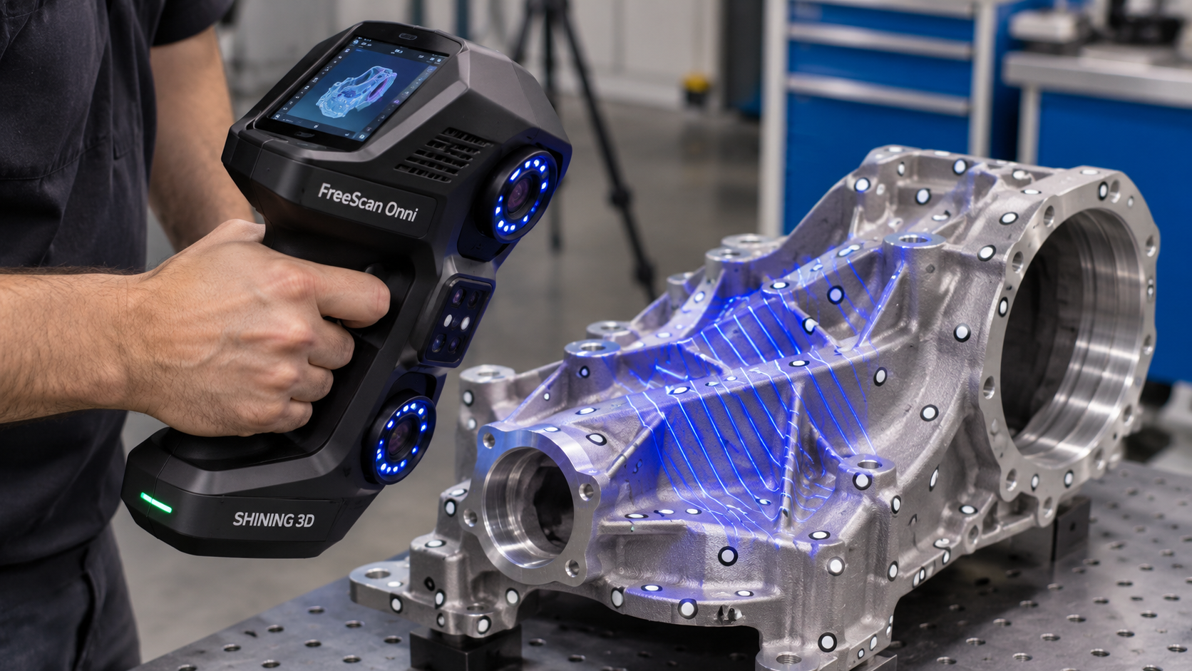
Short answer: Blue-laser scanners and blue structured light scanners both measure surfaces by optical triangulation. A blue-laser scanner moves around the part and depends on retroreflective targets or an optical tracker to hold volumetric accuracy. A structured light scanner captures dense patches from a fixed position and suits smaller parts and repeat inspection. Choose by part size, tolerance and location.
Both technologies show up in the same quote requests, and the spec sheets make them look interchangeable. For metrology, the difference that matters most is how each system ties its measurements to one coordinate system. On parts larger than a shoebox, that is where most scan error comes from.
How a blue-laser scanner measures
A handheld blue-laser scanner projects a set of laser lines onto the part. Two calibrated cameras watch where those lines fall and triangulate each point. Creaform's HandySCAN BLACK Elite, for example, projects 22 blue laser lines and records up to 1.3 million measurements per second.
Triangulation only gives the scanner points relative to itself. To build one model as you walk around a part, the scanner has to know its own position for every frame. On metrology-grade systems that comes from one of two places:
- Retroreflective targets: Placed on the part or on a fixture around it. The cameras see the targets in each frame and the software calculates where the scanner is. Creaform calls this dynamic referencing.
- An external optical tracker: Follows the scan head. This is how the SHINING 3D FreeScan Trak Nova works, the system we run at IMS. The tracker supplies the reference, so normal scanning does not require targets on the part.
This positioning step sets the volumetric accuracy, which is the spec that tells you how error grows with part size. Creaform lists the HandySCAN BLACK Elite at 0.025 mm accuracy and 0.020 mm + 0.040 mm/m volumetric accuracy. On a 2 m part that formula works out to 0.100 mm. Add a photogrammetry frame (Creaform's MaxSHOT) and the figure drops to 0.020 mm + 0.015 mm/m. SHINING 3D lists 0.046 mm + 0.012 mm/m for the Trak Nova with its video photogrammetry. Skip the reference, or place targets badly, and a long part can come back slightly bowed or stretched even though every local surface looks clean.
Some newer scanners offer markerless or feature-tracking modes. They save setup time on scans for visualization or rough reverse engineering. For dimensional inspection against a tight tolerance, we want a measured positioning reference behind the data.
How blue structured light measures
A structured light scanner such as the ZEISS ATOS Q projects a sequence of blue fringe patterns from a fixed head while two cameras record how the fringes bend over the surface. Each shot captures a dense patch. ZEISS lists the ATOS Q 12M at up to 12 million points per scan, point spacing of 0.03 to 0.12 mm, and measuring areas from 100 × 70 mm up to 500 × 370 mm.
The part and scanner have to stay still during each shot. To cover a whole part, the operator takes many shots and stitches them together on reference point targets, usually at least three shared targets per overlap, or on a photogrammetry frame for bigger work. So structured light leans on targets too. It just uses them to join patches instead of tracking a moving scanner.
Side-by-side comparison
| Factor | Blue-laser scanning (handheld) | Blue structured light (fixed head) |
|---|---|---|
| How it measures the surface | Laser lines, stereo camera triangulation | Projected fringe patterns, stereo camera triangulation |
| How it holds position | Retroreflective targets, optical tracker, or photogrammetry | Reference point targets or photogrammetry to stitch shots |
| Typical part size | Roughly 0.05 to 4 m for a handheld scanner (Creaform's recommended range), larger with a tracker or photogrammetry | Small to medium parts per shot, larger parts with stitching and photogrammetry |
| Where it works best | On site, at the machine, in tight access, on parts you cannot move | Lab or cell, parts on a fixture or turntable, repeat inspection |
| Surface detail | Good, adjustable with single-line and fine-line modes | Dense data in each patch, strong on small features |
| Sensitivity to vibration | Lower, the scanner tracks motion | Higher, the setup must stay still during each shot |
| Shiny or dark surfaces | Usually handled with exposure settings and angle, sometimes spray | Exposure control and multiple views, sometimes spray |
| Main accuracy risk | Weak positioning reference on long parts | Stitching error across many shots |
When to choose each
Choose blue-laser scanning when:
- The part is large, heavy or installed, such as a weldment, frame, mold or fixture on the floor.
- You need data at the customer's site or at the machine.
- Access is tight and you need to reach around flanges and into pockets.
- The job is reverse engineering or an as-built capture of something that cannot travel.
Choose blue structured light when:
- The part fits a measuring volume and can sit on a fixture or turntable.
- You inspect the same part number again and again.
- You need dense surface data on small features, such as castings, molded parts or machined details.
Bring in a laser tracker or photogrammetry when the part is too large for a single scanner setup or when you need to tie scan data into an existing coordinate system.
Where scan accuracy is won or lost
The scanner's spec sheet is a starting point. On real parts, these things move the result more:
- Positioning reference. Target layout, tracker placement and photogrammetry control the error on anything larger than one scan patch.
- Temperature. Steel grows about 0.012 mm per meter for every 1 °C. A 5 °C swing on a 1 m steel part is about 0.060 mm, which can eat a tight tolerance on its own.
- Surface prep. Developer spray helps on shiny or dark surfaces but adds thickness. Check that against the tolerance before you spray a machined face.
- Alignment. A best-fit alignment makes a color map look good. GD&T inspection needs the datum reference frame from the drawing, built the way the drawing defines it.
- Point spacing is not accuracy. A scan with points every 0.03 mm is not accurate to 0.03 mm. Ask for volumetric accuracy and acceptance test results to ISO 10360-13 or VDI/VDE 2634.
- Features a scanner cannot see. Deep bores, sharp edges and small holes may need a tactile probe or CMM.
How IMS handles 3D scanning metrology
IMS is a portable metrology services company based in Rockledge, on Florida's Space Coast. We run a SHINING 3D FreeScan Trak Nova for 3D laser scanning, dimensional inspection and reverse engineering and scan to CAD. For large structures and long-range control we have access to FARO, Leica and API laser trackers, and we pair scanning with industrial photogrammetry when a part outgrows a single setup. The same approach supports tooling and fixture certification, where a few datum features matter more than the full surface.
We issue certificates of conformance with our inspection reports. IMS President Zachary Ensley is CMS Certified (Coordinate Metrology Society). We are also an authorized SHINING 3D dealer, so if you are weighing whether to buy a scanner or hire the work out, we can show you both sides on metrology equipment sales.
Frequently asked questions
Do metrology-grade blue-laser scanners need retroreflective targets?
They need a reliable positioning reference. The scanner triangulates the surface on its own, but it needs targets, an optical tracker or photogrammetry to know where it is from frame to frame. Retroreflective targets are the most common method. Tracker-based systems such as the FreeScan Trak Nova do not need targets on the part for normal scanning.
Is a blue-laser scanner more accurate than a structured light scanner?
Neither wins across the board. Structured light gives dense data in each shot on smaller parts. A handheld blue-laser scanner with a good positioning reference holds accuracy better as you move around large or installed parts. Compare volumetric accuracy at your part size, not point count.
What is volumetric accuracy?
It is how measurement error grows with part size, usually written as a fixed term plus a term per meter. For example, 0.020 mm + 0.040 mm/m means about 0.060 mm on a 1 m part and 0.100 mm on a 2 m part, under the manufacturer's test conditions.
Can a 3D scan be used for GD&T inspection?
Yes, when the inspection builds the drawing's datum reference frame and the scanner's accuracy fits the tolerance. A best-fit color map alone is not a GD&T inspection. Some features, such as small deep bores, still need a tactile probe.
When should I use a laser tracker instead of a scanner?
Use a laser tracker when the part or assembly spans several meters, when you need to locate a few critical points tightly, or when scan data must tie into an existing coordinate system. Many jobs use both: the tracker holds the big dimensions and the scanner fills in the surface.
Not sure which method fits your part?
In our experience, most scanning problems trace back to the choice of method or reference, not the scanner itself. If you have a part where you are not sure scanning will hold the tolerance, what is the part size and the tightest callout you need to verify? Send us the drawing through our contact page, email info@fl-ims.com, or call (321) 626-7999. We will tell you plainly whether a blue-laser scan, a laser tracker, a CMM or a mix is the right fit, even when that means you do not need us.
For more on where optical inspection is heading, read 3D Metrology Trends for 2027.
Sources
- Creaform: HandySCAN 3D BLACK Series product page and technical specifications. Accuracy, volumetric accuracy, laser lines, part size, and dynamic referencing. creaform3d.com
- FARO Knowledge Base: Technical Specifications for the HandySCAN BLACK Elite. MaxSHOT volumetric accuracy, measurement rate, and VDI/VDE 2634 Part 3 calibration. knowledge.faro.com
- ZEISS: ATOS Q product specifications. Fringe projection, two cameras, measurement points, point spacing, measuring areas, and Triple Scan. zeiss.com/metrology
- ZEISS Quality Forum and HandsOnMetrology: Measuring large parts with ATOS Q, reference points, and photogrammetry. qualityforum.zeiss.com
- SHINING 3D: Video Photogrammetry technology and FreeScan Trak Nova specifications. shining3d.com
- International Organization for Standardization: ISO 10360-13:2021, acceptance and reverification tests for optical 3D coordinate measuring systems. iso.org